
- Catalogs
- Di.Bi. Porte Blindate
- security doors istallation solutions technical drawings

- Company
- Products
- Catalogs
- News & Trends
- Exhibitions
security doors istallation solutions technical drawings
security doors istallation solutions technical drawings
Document Overview
This technical document from DI.BI. PORTE BLINDATE Srl (Italy) version 4.6 dated February 16, 2026, provides comprehensive specifications, sectional drawings, and installation guidelines for security door frames and subframes. It covers multiple door models, frame types, glazing options, and installation solutions with emphasis on structural integrity, thermal and acoustic performance, and aesthetic integration.
Main Sections and Summaries
1. Threshold Sections and Subframe Installation
- Details vertical and horizontal threshold sections for subframe installation with variations for different flooring types.
- Standard subframe height is 2159 mm with reference door height 2100 mm.
- Threshold dimensions differ by frame material: 13 mm for steel, 16 mm for aluminum, increased by 20 mm for watertight, soundproof, and thermal break thresholds.
- Options include weatherstrip bars, drip rails, and thermal break thresholds to enhance sealing and insulation.
2. Standard Subframe "CT1" and Variants
- Standard "CT1" subframe features removable corner gussets and spreaders for installation flexibility.
- Variants include watertight/sound/thermal break thresholds with increased dimensions (+20 mm).
- Specialized "CT1" subframe designed for "884" security door with flush plaster installation and 45° angled edges.
3. Standard Subframe "CT1" with Frame and Window Sections
- Horizontal and vertical sections for door models A through H with standard frames.
- Configurations include side and top windows, fixed glazed lateral panels, and arched top windows.
- Maximum glazed area dimensions specified per model (e.g., 2000x2850 mm for model B).
- Details on door passage widths, clear view widths, impost glazed heights, and options for concealed hinges and thermal break thresholds.
4. Smaller Subframes "CT3" and "CT3.1"
- Reduced subframe solutions for narrower installations with standard and bicolour aluminum frames.
- Includes side and top window configurations.
5. Subframe Extensions and Reduced Extensions
- Subframes with extensions "CT2" and reduced extension "CT4" for specific installation needs.
- Solutions combine standard and aluminum frames with extension linings.
6. Aluminum Frame Solutions
- One-colour aluminum frames flush with the wall, with side and top windows.
- Frames with watertight, soundproof, and thermal break thresholds.
- Thermal break aluminum frames incorporating glass side and top windows.
7. Box-Shaped Frame Solutions
- Box-shaped frames with external covering profiles and extension linings.
- Variants include concealed hinges and flush with wall installation.
8. Pivot Security Door Frames
- Subframe and frame solutions for DI.BIG pivot security doors with various interior and exterior wall finishes.
- Flush with wall solutions including blind and glazed side/top windows.
- Push door assembly schemes for standard DI.BIG panels.
9. Door Opening Schemes
- Push and pull door opening configurations for right and left sides, internal and external.
Critical Specifications and Parameters
- Standard subframe height: 2159 mm; reference door height: 2100 mm.
- Threshold dimensions: 13 mm (steel), 16 mm (aluminum), increased by 20 mm for watertight/sound/thermal break thresholds.
- Rough opening and subframe width dimensions detailed per configuration.
- Removable corner gussets and spreaders facilitate installation and adjustment.
- Maximum glazed area dimensions vary by door model; clear view widths and heights specified.
- Installation recommendations include flush plastering and angled edges for specific security doors.
Installation Recommendations and Best Practices
- Use removable spreaders and gussets to ease installation and alignment.
- Ensure proper sealing with weatherstrip bars and drip rails to enhance watertightness and acoustic performance.
- Increase subframe dimensions by 20 mm when using thermal break thresholds to maintain performance.
- Adhere strictly to specified rough opening dimensions for correct fitting and security.
- Use concealed hinges where specified for improved aesthetics and security.
- Flush with wall installation is recommended for certain models to improve integration with building finishes.
Summary of Technical Drawings
The document includes detailed scaled drawings (scales 1:1 to 1:100) illustrating:
- Threshold cross-sections showing weatherstrip and drip rail placements.
- Subframe cross-sections with dimensions for rough openings, splay, and fixing points.
- Door models with side and top glazed panels, including various arched top window styles.
- Pivot door frame solutions with flush wall integration.
These drawings serve as precise guides for manufacturing, installation, and quality control.
Door and Glazed Area Specifications
- Door widths range from 700 mm to 2000 mm; heights from 2000 mm to 2700 mm depending on model.
- Maximum glazed area dimensions up to 1800 mm width x 2850 mm height.
- Top window dimensions vary by model, often calculated as (Glazed Area Width / 2) + 90 mm.
- Side windows present in some models with minimum widths of 200 mm and typical sizes around 250-300 mm.
- Glazed area dimensions vary by model, e.g., 900x2920 mm for model B, 1300x2920 mm for model E.
Subframe Types and Frame Solutions
- Standard subframe "CT1" used with standard frames, including watertight, soundproof, and thermal break thresholds.
- Subframe with extension "CT2" designed for larger or complex door assemblies.
- Smaller subframe "CT3" for narrower installations.
- Frame materials include steel and bicolour aluminum frames.
Window and Arch Schemes
- Various top window arch styles: segmental arched, stilted segmental arched, round arched, and stilted round arched.
- Each arch style includes dimensional constraints and glazing area calculations.
- Top window dimensions linked to glazed area width for proportional design.
Sectional Views and Installation Details
- Horizontal and vertical sectional drawings illustrate frame profiles, glazing bead positions, and threshold details.
- Dimensions for clear openings, rough openings, frame sizes, and splay measurements provided.
- Invisible hinges noted in some solutions.
- Fixing clips, removable spreaders, and corner gussets standard for installation.
Dimensional Parameters and Clearances
- Clear opening widths typically around 885-936 mm for 900 mm door width.
- Rough opening dimensions exceed clear openings to accommodate frames.
- Minimum clearances for glazing and side windows defined (side windows minimum width 200 mm, top windows minimum height 200 mm).
- Passage heights around 2100 mm; overall frame heights up to 2940 mm depending on model.
Recommendations and Best Practices
- Calculate top window dimensions based on glazed area width for design consistency.
- Respect minimum dimensions for side and top windows for structural integrity and aesthetics.
- Use watertight, soundproof, and thermal break thresholds for enhanced performance.
- Employ removable spreaders and gussets to facilitate installation.
Summary of Model Differences
- Model B: 900 mm wide door, various top window heights, minimal or no side windows.
- Model E: Includes side windows (minimum 200 mm width) alongside top windows, glazed areas up to 1500 mm wide.
- Models C, D, F, G, H: Variations in glazed area sizes and configurations, often with fixed lateral glazed panels.
Frame and Subframe Types
- Preframe types include reduced preframes "CT3" and "CT3.1", standard frames, and box-shaped frames with external covering.
- Materials: steel, bicolour and one-colour aluminum frames.
- Subframe features removable corner gussets and spreaders for ease of installation.
- Frame extensions include reduced and full extensions with marble and aluminum finishes.
Sectional Views and Construction Details
- Vertical and horizontal sections at scales 1:1 to 1:3 show door profiles, frame assembly, and glazing integration.
- Imposed glazed transoms with specified heights (e.g., 300 mm).
- Clear and rough opening dimensions detailed, including allowances for rubber cushions and splay.
- Watertight, soundproof, and thermal break thresholds specified for aluminum frames flush with the wall.
Installation Solutions and Recommendations
- Multiple installation solutions including internal splay, exposed wooden or marble extension linings, and aluminum extension linings.
- Minimum wall thickness and extension lining sizes specified (e.g., minimum 40 mm on three sides).
- Use silicone sealing and plastic covers for airtightness and aesthetic finish.
- Concealed hinges available in box-shaped frames for security and appearance.
Side and Top Window Integration
- Side windows with minimum widths 200-300 mm and rough opening heights detailed.
- Top windows (imposte) with specified heights (e.g., 300 mm) integrated into door assemblies.
- Clear and rough opening dimensions coordinated with door frames for structural and visual consistency.
Critical Parameters and Limitations
- Door width range: 700-2000 mm; height range: 2000-2700 mm depending on model.
- Maximum overall door and window dimensions capped at 5000x5000 mm.
- Minimum clearances for installation components such as rubber cushions, splay, and sealing materials.
- Dimensional tolerances for rough openings critical for fitting and performance.
Best Practices and Recommendations
- Select appropriate preframe and frame solutions based on wall thickness and finishing requirements.
- Use removable spreaders and gussets to facilitate installation and adjustment.
- Ensure watertight, soundproof, and thermal break thresholds for enhanced performance.
- Coordinate glazing dimensions with door frame for security and aesthetics.
- Apply silicone sealing and plastic covers to protect against environmental factors and improve finish.
Pivot Door Frame Solutions
- Door widths from 1100 mm to 1800 mm; heights from 2100 mm to 2800 mm.
- Finishing solutions include exterior wall finish with laminated panels, interior plaster/boiserie detailing, and flush with wall installations.
- Door models A through N with variations in glazed areas, side and top windows (blind or glazed).
- Push door assembly schemes for right-hand and left-hand doors with proportional panel widths.
Materials and Finishes
- Frames use aluminum with thermal breaks, polystyrene polymer insulation, and Techsound soundproofing.
- Finishing panels include "LAMINAM" for interior and exterior surfaces.
- Silicone splay used extensively for sealing and waterproofing.
- Watertight thresholds specified for aluminum frame solutions.
Assembly and Installation Notes
- Detailed panel width proportions and clear opening calculations provided.
- Project feasibility for large pivot doors (>2800 mm height) evaluated case-by-case.
- Subframes dimensioned to fit rough openings and support various wall finishes.
Summary of Key Dimensions (Example Model "A" with 900 mm Door Width)
| Parameter | Dimension (mm) |
|---|---|
| Clear Opening Width | 900 |
| Rough Opening Width | 984 - 1053 (varies by solution) |
| Frame Overall Width | 1041 - 1053 |
| Door Height | 2100 - 2450 |
| Glazed Area Width | 895 - 1495 |
| Glazed Area Height | 2092 - 2418 |
| Minimum Frame Thickness | 50 - 60 |
Conclusion
This document is a comprehensive technical guide for DI.BI. security doors, covering multiple models and configurations. It emphasizes dimensional accuracy, material selection, and installation details to ensure optimal door performance, durability, and aesthetic integration. The inclusion of thermal and soundproof thresholds, glazing options, and flush with wall solutions highlights adaptability to modern architectural requirements.
Manufacturer Information
DI.BI. PORTE BLINDATE Srl, Fano (PU), Italy
Website: www.dibigroup.com
Catalog excerpts
FRAMES and SUBFRAMES SECURITY DOORS TECHNICAL DRAWINGS rev. 2026.02.12
Open the catalog to page 1
FRAMES and SUBFRAMES SECURITY DOORS TECHNICAL DRAWINGS rev. 2026.02.16
Open the catalog to page 3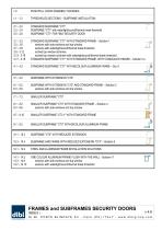
PUSH/PULL DOOR ASSEMBLY SCHEMES THRESHOLDS SECTIONS – SUBFRAME INSTALLATION STANDARD SUBFRAME "CT1" SUBFRAME "CT1" with watertight/sound/thermal break threshold SUBFRAME "CT1" FOR "884" SECURITY DOOR STANDARD SUBFRAME "CT1" WITH STANDARD FRAME – Solution 1 sections with side windows and top window sections with watertight/sound/thermal break threshold arched top window schemes arched top window schemes with watertight/sound/thermal break threshold STANDARD SUBFRAME "CT1" WITH STANDARD FRAME, WITH CONCEALED HINGES – Solution 1a STANDARD SUBFRAME "CT1" WITH BICOLOUR ALUMINIUM FRAME – Sol. 8 SUBFRAME...
Open the catalog to page 4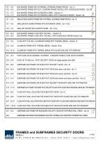
16.1 - 16.2 BOX-SHAPED FRAME WITH EXTERNAL COVERING-FRAME PROFILE - Sol. 13 JJ 16.3 - 16.4 BOX-SHAPED FRAME WITH EXT. COVERING-FRAME PROFILE, WITH CONCEALED HINGES - Sol.13a 17.1 - 17.2 BOX-SHAPED FRAME WITH EXTENSION LINING - Solution 14 ™ 17.3.- 17.4 BOX-SHAPED FRAME WITH EXTENSION LINING, WITH CONCEALED HINGES - Solution 14a 18.1 - 18.2 SMALLER BOX-SHAPED FRAMEWITH EXTERNAL COVERING-FRAME PROFILE-Sol. 15 19.1 - 19.2 SMALLER BOX-SHAPED FRAME WITH EXTENSION LINING - Sol. 15 bis 19.3 - 19.4 SMALLER WELDED BOX-SHAPED FRAME - Sol. 15 tris 20.1 - 20.2 BOX-SHAPED FRAME FLUSH WITH THE WALL - Solution...
Open the catalog to page 5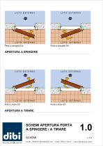
LATO ESTERNO SCHEMI APERTURA PORTA A SPINGERE / A TIRARESCHEMI v 1.0 DI.BI. PORTE BLINDATE Srl - Fano (PU) ITALY - www.dibigroup.com
Open the catalog to page 6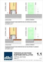
EXTERNAL SIDE subframe installation vertical section EXTERNAL SIDE EXTERNAL SIDE STANDARD DOOR WITH WEATHERSTRIP BAR ON CONTINUOUS FLOORING SUBFRAME H =2159 ref. DOOR H=2100 vertical section subframe installation STANDARD DOOR WITH WEATHERSTRIP BAR ON TWO DIFFERENT FLOORINGS SUBFRAME H =2159 ref. DOOR H=2100 THRESHOLDS SECTIONS SUBFRAME INSTALLATION VERTICAL SECTIONS scale 1:2 DI.BI. PORTE BLINDATE Srl - Fano (PU) ITALY - www.dibigroup.com
Open the catalog to page 7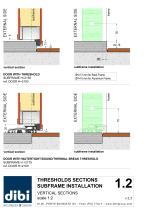
EXTERNAL SIDE EXTERNAL SIDE vertical section EXTERNAL SIDE D1=13 mm for Steel Frame D1=16 mm for Aluminium Frame EXTERNAL SIDE DOOR WITH THRESHOLD SUBFRAME H=2159 ref. DOOR H=2100 subframe installation DOOR WITH WATERTIGHT/SOUND/THERMAL BREAK THRESHOLD SUBFRAME H =2179 ref. DOOR H=2100 THRESHOLDS SECTIONS SUBFRAME INSTALLATION VERTICAL SECTIONS scale 1:2 DI.BI. PORTE BLINDATE Sr l - Fano (PU) ITALY - www.dibigr oup.c om
Open the catalog to page 8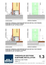
EXTERNAL SIDE subframe installation vertical section EXTERNAL SIDE EXTERNAL SIDE DOOR WITH THRESHOLD, WEATHERSTRIP BAR AND DRIP RAIL FOR STANDARD SUBFRAME ON CONTINUOUS FLOORING SUBFRAME H=2159 - ref. DOOR H=2100 vertical section subframe installation DOOR WITH THRESHOLD, WEATHERSTRIP BAR AND DRIP RAIL FOR STANDARD SUBFRAME ON TWO DIFFERENT FLOORINGS SUBFRAME H=2159 - ref. DOOR H=2100 THRESHOLDS SECTIONS SUBFRAME INSTALLATION VERTICAL SECTIONS scale 1:2 DI.BI. PORTE BLINDATE Srl - Fano (PU) ITALY - www.dibigroup.com
Open the catalog to page 9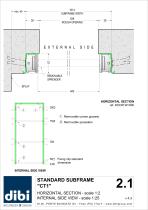
ROUGH OPENING © Removable corner gussets 1520 (2 Removable spreaders HORIZONTAL SECTION ref. DOOR W=900 50(*) Fixing clip standard 000 dimension INTERNAL SIDE VIEW STANDARD SUBFRAME"CT1" 2.1HORIZONTAL SECTION - scale 1:2INTERNAL SIDE VIEW - scale 1:25 v 4.3 DI.BI. PORTE BLINDATE Srl - Fano (PU) ITALY - www.dibigroup.com
Open the catalog to page 10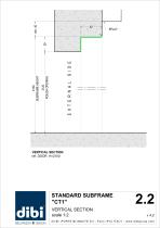
VERTICAL SECTION ref. DOOR H=2100 STANDARD SUBFRAME "CT1" VERTICAL SECTION scale 1:2 DI.BI. PORTE BLINDATE Srl - Fano (PU) ITALY - www.dibigroup.com
Open the catalog to page 11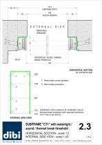
REMOVABLE SPREADER WATERTIGHT, SOUND, THERMAL BREAK THRESHOLD 943 HORIZONTAL SECTION ref. DOOR W=900 1 1 Removable corner gussets 70(*) Verification of the measure for watertight, sound, thermal break threshold (with standard subframe 0.00 "CT1" has to be 50mm) INTERNAL SIDE VIEW SUBFRAME "CT1" with watertight / sound / thermal break threshold HORIZONTAL SECTION - scale 1:2 INTERNAL SIDE VIEW - scale 1:25 DI.BI. PORTE BLINDATE Sr l - Fano (PU) ITALY - www.dibigr oup.c om
Open the catalog to page 12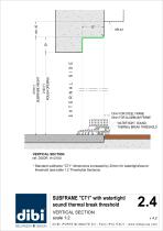
13mm FOR STEEL FRAME 16mm FOR ALUMINIUM FRAME WATERTIGHT, SOUND, THERMAL BREAK THRESHOLD VERTICAL SECTION * Standard subframe "CT1" dimensions increased by 20mm for watertight/sound threshold (see table 1.2 Thresholds Sections) SUBFRAME "CT1" with watertight/sound/ thermal break threshold 2.4VERTICAL SECTIONscale 1:2 v 4.2 DI.BI. PORTE BLINDATE Srl - Fano (PU) ITALY - www.dib
Open the catalog to page 13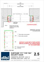
REMOVABLE SPREADER SPLAY FLUSH WITH PLASTER PROTECTION FOR FIXED DEADBOLTS AND LATERAL DEADBOLTS HORIZONTAL SECTION ref. DOOR W=900 1 1 Removable corner gussets NOTICE! FLUSH WITH THEPLASTER INSTALLATION AT 45° ANGLE EDGE OF THE SUBFRAME 50(*) Fixing clip standard dimension 0.00 INTERNAL SIDE VIEW SUBFRAME "CT1" FOR "884" SECURITY DOOR HORIZONTAL SECTION - scale 1:2 INTERNAL SIDE VIEW - scale 1:25 DI.BI. PORTE BLINDATE Sr l - Fano (PU) ITALY - www.dibigr oup.c om
Open the catalog to page 14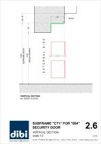
VERTICAL SECTION ref. DOOR H=2100 SUBFRAME "CT1" FOR "884" SECURITY DOOR VERTICAL SECTION scale 1:2 DI.BI. PORTE BLINDATE Srl - Fano (PU) ITALY - www.dibigroup.com
Open the catalog to page 15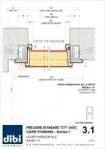
1014 CÔTE FOND DE FEUILLURE 936 CÔTE TABLEAU CÔTÉ EXTÉRIEUR 1044 LARGEUR HORS-TOUT CADRE COUPE HORIZONTALE DE LA PORTE MODÈLE "A" réf.PORTE L=900 Cochonnet L=18 PRÉCADRE STANDARD "CT1" AVEC CADRE STANDARD – Solution 1 COUPE HORIZONTALE échelle 1:2 DI.BI. PORTE BLINDATE Sr l - Fano (PU) ITALY - www.dib
Open the catalog to page 16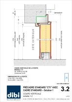
2172 HAUTEUR HORS-TOUT CADRE CÔTÉ EXTÉRIEUR 2159 CÔTE FOND DE FEUILLURE COUPE VERTICALE DE LA PORTE MODÈLE "A" réf. PORTE H=2100 Cochonnet H=20 DIMENSIONS DE LA PORTE: L=min.700 - max.2000 H=min.2000 - max.2700 PRÉCADRE STANDARD "CT1" AVEC CADRE STANDARD – Solution 1 COUPE VERTICALE échelle 1:2 DI.BI. PORTE BLINDATE Srl - Fano (PU) ITALY - www.d
Open the catalog to page 17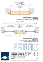
CÔTÉ EXTÉRIEUR LCV = 900 LARGEUR CLAIR DE VUE 900 COUPE HORIZONTALE DE LA PORTE MODÈLE "B" réf.PORTE L=900 - LARGEUR CLAIR DE VUE LCV=900 18 300 (MIN 200) FIXE LATÉRAL VITRÉ CÔTÉ EXTÉRIEUR LCV=1500 LARGEUR CLAIR DE VUE 900 18 300 (MIN 200) FIXE LATÉRAL VITRÉ 216 (MIN 116) COUPE HORIZONTALE DE LA PORTE MODÈLES "E-F" réf.PORTE L=900 - FIXE LATÉRAL VITRÉ 300 LARGEUR CLAIR DE VUE LCV=1500 PRÉCADRE STANDARD "CT1" AVEC CADRE STANDARD – Solution 1 COUPES HORIZONTALES échelle 1:5 DI.BI. PORTE BLINDATE Sr l - Fano (PU) ITALY -
Open the catalog to page 18Archived catalogs
 OUR SELECTION
13 Pages
 Catalogue Di.Bi. Security doors
63 Pages

- Dibi swing door
- Wooden door
- Dibi contemporary door
- Dibi door without glazing
- Dibi 1 leaf door
- Dibi metal door
- Dibi entry door
- Dibi custom door
- Glazed door
- Aluminum door
- Dibi insulated door
- Lacquered door
- Dibi acoustic door
- Dibi white door
- Dibi decorative door
- Dibi flush door
- Double leaf door
- Dibi customizable color door