
- Catalogs
- Delta Energy Systems
- SOLIVIA 10 TL

SOLIVIA 10 TL

SOLIVIA 10 TL
Catalog excerpts

Operation and Installation manual SOLIVIA 10 EU T4 TL SOLIVIA 15 EU G4 TL SOLIVIA 20 EU G4 TL SOLIVIA 30 EU T4 TL
Open the catalog to page 1
This manual is subject to change. Please check our website at www.solar-inverter.com for the most up-to-date manual version. © Copyright – Delta Energy Systems (Germany) GmbH - All rights reserved. This manual accompanies our equipment for use by the end users. The technical instructions and illustrations contained in this manual are to be treated as confidential and no part may be reproduced without the prior written permission of Delta Energy Systems Service engineers and end users may not divulge the information contained herein or use this manual for purposes other than those strictly connected...
Open the catalog to page 3
Table of Contents 1. General Safety Instructions . . . . . . . . . . . . . . . . . . . . . . . . . . 11 2. General Information . . . . . . . . . . . . . . . . . . . . . . . . . . . . . . . 24 2.1 About this Manual . . . . . . . . . . . . . . . . . . . . . . . . . . . . 24 Safety Symbols & Instruction . . . . . . . . . . . . . . . . . . . . . . 24 Instruction before Installing . . . . . . . . . . . . . . . . . . . . . . . 28 4.3.1 LCD Display and Buttons . . . . . . . . . . . . . . . . . . . . . . . . 35 4.3.2 Inverter Input/Output Interface . . . . . . . . . . . . . . . . . . . . . . 36 4.3.3...
Open the catalog to page 4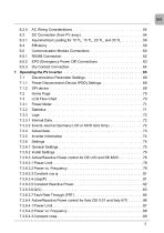
DC Connection (from PV array) . . . . . . . . . . . . . . . . . . . . . 54 Communication Module Connections . . . . . . . . . . . . . . . . . . 60 6.5.1 RS485 Connection . . . . . . . . . . . . . . . . . . . . . . . . . . . . 62 6.5.2 EPO (Emergency Power Off) Connections . . . . . . . . . . . . . . . 63 6.5.3 Dry Contact Connection . . . . . . . . . . . . . . . . . . . . . . . . . 64 7. Operating the PV inverter . . . . . . . . . . . . . . . . . . . . . . . . . . . 65 7.1 Disconnection Parameter Settings . . . . . . . . . . . . . . . . . . . . 68 7.1.1 Power Disconnection Device (PDD) Settings...
Open the catalog to page 5
7.3.6.4.4 cosφ(P) . . . . . . . . . . . . . . . . . . . . . . . . . . . . . . . . . . . . . . . . . . . . . . . . . 89 7.3.6.4.5 Constant Reactive Power . . . . . . . . . . . . . . . . . . . . . . . . . . . . . . . . . . . 92 7.3.6.4.6 Q(V) . . . . . . . . . . . . . . . . . . . . . . . . . . . . . . . . . . . . . . . . . . . . . . . . . . . .92 7.3.6.4.7 LVFRT Low Voltage Fault Ride Through (LVFRT) . . . . . . . . . . . . . . . . 94 7.3.6.5 Reactive Power Control for Slovenia (SONDO) for 15 / 20 / 30 15 TL and 20 TL Models With Earlier DC Input Panel . . . . . . . . . .118
Open the catalog to page 6
Figures Figure 2.1.: Solar Inverter System Operation Illustration . . . . . . . . . . . . . 26 Figure 3.1.: Unpacking Process . . . . . . . . . . . . . . . . . . . . . . . . . . 29 Figure 3.2.: The Type Label 10 TL and 15 TL . . . . . . . . . . . . . . . . . . . 30 Figure 3.3.: The Type Label 20 TL and 30 TL . . . . . . . . . . . . . . . . . . . 30 Figure 4.1.: Dimensions of SOLIVIA 10 TL . . . . . . . . . . . . . . . . . . . . 31 Figure 4.2.: Dimensions of SOLIVIA 15 TL / 20 TL / 30 TL . . . . . . . . . . . . 32 Figure 4.3.: 10 TL Inverter Exterior View . . . . . . . . . . . . . . . . . . ....
Open the catalog to page 7
Figure 6.13.: SOLIVIA 20 TL Efficiency Curve . . . . . . . . . . . . . . . . . . . 59 Figure 6.14.: SOLIVIA 30 TL Efficiency Curve . . . . . . . . . . . . . . . . . . . 60 Figure 6.15.: Communication module removal . . . . . . . . . . . . . . . . . . . 61 Figure 6.16.: Multi-inverter connection illustration . . . . . . . . . . . . . . . . . 62 Figure 6.17.: Terminal resistor switch for Multi-inverter Connection . . . . . . . . 63 Figure 6.18.: Dry contact connection . . . . . . . . . . . . . . . . . . . . . . . . 64 Figure 7.1.: Country Settings on initial startup . . . . . . . . . . . . . ....
Open the catalog to page 8
Figure 7.32.: cos φ(P) settings page . . . . . . . . . . . . . . . . . . . . . . . . 91 Figure 7.33.: Constant Reactive Power settings page . . . . . . . . . . . . . . . 92 Figure 7.34.: Q(V) . . . . . . . . . . . . . . . . . . . . . . . . . . . . . . . . . . 93 Figure 7.35.: Q(V) Settings Page . . . . . . . . . . . . . . . . . . . . . . . . . . 93 Figure 7.36.: Low Voltage Fault Ride Through graph . . . . . . . . . . . . . . . . 94 Figure 7.37.: Fault Ride Through settings page . . . . . . . . . . . . . . . . . . . 95 Figure 7.38.: SONDO Class B curve . . . . . . . . . . . . . . . . . . . ....
Open the catalog to page 9
Cable cross sections and torques for AC connectors . . . . . . . . . 48 Permitted earthing systems . . . . . . . . . . . . . . . . . . . . . . 49 Recommended settings of protection equipment as per BDEW Technical Guidelines - June 2008 issue from Table 3.2.3.3 - 2 . . . . 69 Home Page Measurements and Description . . . . . . . . . . . . .102 Power Meter Pages Measurements and Description . . . . . . . . 103 Statistics Pages Measurements and Description . . . . . . . . . . 104 Actual Data Pages Measurement and Description . . . . . . . . . .106 Temperature Measurement and Description . . . . ....
Open the catalog to page 10
General Safety Instructions General Safety Instructions English Danger Risk of death by electrocution Potentially fatal voltage is applied to the solar inverter during operation. This potentially fatal voltage is still present for five minutes after all power sources have been disconnected. ►► Never open the solar inverter. ►► Always disconnect the solar inverter from power before installation, open the DC isolating switch and make sure neither can be accidentally reconnected. ►► Wait at least five minutes until the capacitors have discharged. Danger Risk of death or serious injury from electrocution...
Open the catalog to page 11
General Safety Instructions ●● To prevent lightning strikes, follow the relevant regulations applicable in your country. The surface of the solar inverter can become very hot. The solar inverter is very heavy. The solar inverter must be lifted and carried by at least two people. Only devices in compliance with SELV (EN 69050) may be connected to the RS485 and USB interfaces. All connections must be sufficiently insulated in order to comply with the IP65 protection rating. Unused connections must be closed by placing cover caps on the solar inverter. Allgemeine Sicherheitsanweisungen Gefahr Lebensgefahr...
Open the catalog to page 12All Delta Energy Systems catalogs and technical brochures
 Solar Product Overview 2024
12 Pages
 M70A Flex
2 Pages
 M125HV_111 Gen2
2 Pages
 M15A
M15A2 Pages
 M50A
M50A2 Pages
 M30A
M30A2 Pages
 M20A
M20A2 Pages
 H2.5 Flex
2 Pages
 DC1 Data Collector
2 Pages
 DC1
DC12 Pages
 M125HV
2 Pages
 SOLIVIA Monitor
36 Pages
 RPI M50A
2 Pages
 M88H
M88H2 Pages
 H3 Flex
2 Pages
 RPI M20A
2 Pages
 RPI M15A
2 Pages
 RPI M10A
2 Pages
 RPI M30A
2 Pages
 RPI H3
2 Pages
 RPI M8A
2 Pages
 RPI M6A
2 Pages
 RPI H5A
2 Pages
 RPI H4A
2 Pages
 SOLIVIA 10 TR
6 Pages
 SOLIVIA 2.0 EU G4 TR
48 Pages
 SOLIVIA 30 TL
2 Pages
 SOLIVIA 15 TL and 20 TL
28 Pages
 SOLIVIA 5.0 EU G4
48 Pages
 SOLIVIA 3.6 EU G4
48 Pages
 SOLIVIA 3.3 EU G4
48 Pages
 SOLIVIA 3.0 EU G4
48 Pages
 SOLIVIA 2.5 EU G4
48 Pages
 SOLIVIA 3.3 EU G3
48 Pages
 SOLIVIA 3.0 EU G3
48 Pages
 SOLIVIA 2.5 EU G3
48 Pages
 SOLIVIA 3.6 TR
2 Pages
 ASP
ASP20 Pages


Archived catalogs
 Solar Inverter 2019
6 Pages
 Solar Inverter 2022
8 Pages


- Design software
- String inverter
- Three-phase inverter
- Industrial monitoring system
- Transformerless inverter
- Single-phase inverter
- Wireless monitoring system
- Energy meter
- Photovoltaïc installation monitoring system
- Residential installation inverter
- Photovoltaïc installation software
- Single-phase energy meter
- Three-phase energy meter
- Modular inverter
- Residential inverter
- Residential energy meter
- Solar tracking monitoring system