


6000XL & 6100XL Series Reach Ins

6000XL & 6100XL Series Reach Ins
This manual provides essential guidelines for the installation, operation, and maintenance of the 6000XL and 6100XL Series Reach-In Refrigerators and Freezers. It is important to read the manual thoroughly before installation or operation.
Upon receipt, inspect the packaging for damage. Report any damage to the carrier and inspect the contents with them. Retain packaging materials until inspection is complete.
The manual details specifications for various models, including voltage, amperage, storage capacity, and shipping weight. For instance, the 6025XL-SH,S model operates at 115 volts with a 20.0 cubic feet storage capacity and a shipping weight of 274 lbs.
Ensure stable installation with locked front wheels. Allow 24 hours before startup if the unit was laid on its side or back. Electrical connections must comply with local and National Electrical Codes. Maintain at least 2 inches of clearance from walls and 12 inches above.
Instructions for reversing door hinges include removing and remounting hinges and locks. Ensure proper closure and gasket seal after reinstallation.
The electronic temperature control maintains consistent temperatures and displays errors if they occur. Freezers enter a defrost mode upon initialization, which may take up to 15 minutes. Temperature alarms flash if temperatures exceed set points.
Regular maintenance is crucial for optimal performance, including checking the evaporator fan matrix and ensuring proper air circulation inside and outside the cabinet.
The manual includes wiring diagrams and a list of replacement parts for troubleshooting and repairs.
Labor guidelines and standard warranties emphasize the importance of proper installation and maintenance to avoid voiding warranties.
The document lists parts for the 6000XL Series, including compressors, capacitors, filters, solenoid valves, and replacement parts for stainless steel and glass doors, with part numbers and compatibility details.
Standard labor guidelines for repairing or replacing parts specify maximum times for diagnosing defects, retrieving parts, and travel reimbursements. Specific labor times are allocated for replacing components like thermostats, fan motors, solenoid valves, and compressors.
Delfield offers a limited lifetime warranty on ABS interior liners for the 6000XL Series, covering defects under normal use for products sold and installed after March 1, 2000, in the US, Canada, Puerto Rico, and Mexico. The document outlines user responsibilities, claim procedures, and exclusions, emphasizing the use of approved replacement parts and adherence to guidelines.
The warranty excludes labor, service charges, or defects from misuse, improper installation, or maintenance. It also excludes non-approved parts and modifications. The document disclaims implied warranties of merchantability or fitness for a particular purpose and limits liability for incidental or consequential damages.
Delfield offers a standard one-year warranty covering parts and labor. Additional service agreements or services can be purchased at current rates. More details are available on their website.
Delfield provides customer support via phone. Customers should have their model and serial numbers ready when calling for assistance.
Delfield's contact details include their address in Mt. Pleasant, MI, and phone numbers for customer service. A list of authorized parts depots is available on their website.
Delfield reserves the right to change designs or specifications without notice.
Catalog excerpts
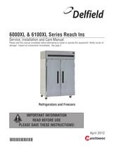
Service, Installation and Care Manual Please read this manual completely before attempting to install or operate this equipment! Notify carrier of damage! Inspect all components immediately. See page 2. PLEASE SAVE THESE INSTRUCTIONS!
Open the catalog to page 1
6000XL Series Service and Installation Manual Serial Number Information The serial number tag of all 6000XL Series refrigerators and freezers is located inside the cabinet on the left side. Always have the serial number of your unit available when calling for parts or service. A complete list of authorized Delfield parts depots is available at www.delfield.com. This manual covers standard units only. If you have a custom unit, consult the customer service department at the number listed below. ©2012 The Delfield Company. All rights reserved. Reproduction without written permission Is prohibited....
Open the catalog to page 2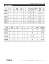
6000XL Series Service and Installation Manual For customer service, call (800) 733-8829, (800) 733-8821, Fax (888) 779-2040, www.delfield.com
Open the catalog to page 3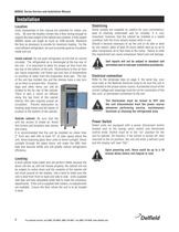
6000XL Series Service and Installation Manual Units represented in this manual are intended for indoor use only. Be sure the location chosen has a floor strong enough to support the total weight of the cabinet and contents. A fully loaded 6000XL series can weigh as much as 1500 pounds. Reinforce the floor as necessary to provide for maximum loading. For the most efficient refrigeration, be sure to provide good air circulation Inside cabinet: Do not pack refrigerator so full that air cannot circulate. The refrigerated air is discharged at the top rear of the unit. It is important to allow for...
Open the catalog to page 4
6000XL Series Service and Installation Manual Door Reversal Procedures Standard Edge-Mount Hinge 1. Open door 90° and lift door straight up and off hinges. 2. Remove the metal screw covers on each door-side hinge section by sliding it down and off. 3. Remove two outer screws that mount each hinge to door loosen the center screw, rotate hinge 180°, reinstall outer screws and retighten centerscrew. 4. Remove two screws that mount lock on top of door, turn door up-side-down and remount lock to top of door. 5. Use a 3/16" drill to drill holes in cabinet face frame at the marked hinge locations on...
Open the catalog to page 5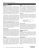
6000XL Series Service and Installation Manual Electronic Temperature Control The electronic temperature control constantly monitors box temperature as well as evaporator coll temperature to maintain consistent product temperatures. The control also sends temperature readings to the digital temperature display. The control circuits continually self-check and If an error occurs, the digital display will switch from temperature read-out to error read-out, I.e. E 1. Even when an error Is displayed, the refrigeration and controls system should continue to function, however not at optimal performance....
Open the catalog to page 6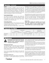
6000XL Series Service and Installation Manual Operation, continued Whenever the freezer is plugged in, and the control has completed initializing including the initial defrost cycle (also see Electronic Temperature Control Operation, on this page). The digital therostat will display box temperature. The temperature control will cycle the compressor, evaporator fan motor and condenser fan motor to maintain box temperature at the control setting. See evaporator fan matrix for more information. Freezer Automatic Defrost The control also monitors compressor total running time and will enter a defrost...
Open the catalog to page 7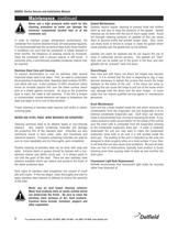
6000XL Series Service and Installation Manual Maintenance, continued A Never use a high pressure water wash for this cleaning procedure as water can damage the ^Ka^ electrical components located near or at the CAUTION condenser coil. In order to maintain proper refrigeration performance, the condenser fins must be cleaned of dust, dirt and grease regularly. It is recommended that this be done at least every three months. If conditions are such that the condenser is totally blocked in three months, the frequency of cleaning should be increased. Clean the condenser with a vacuum cleaner or stiff...
Open the catalog to page 8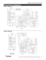
6000XL Series Service and Installation Manual REVISIONS REV 9294455 NOTES: 1) USE COPPER CONDUCTORS ONLY 2) THIS UNIT MUST BE GROUNDED 3) UNIT SHOWN WITH COMPRESSOR RUNNING AND DOORS CLOSED N LINE VOLTAGE 115/60/1 SEE NAMEPLATE FOR MAXIMUM FUSE SIZE 26-MAY-2011 L ENNIS M Y N 5 BLUE F M 6 FAN RELAY PLUG DEFROST HEATER EVAP COIL SENSOR CONTROL CIRCUIT W EVAPORATOR FAN INCANDESCENT LIGHT H 4 HEATER RELAY C M COMPRESSOR W WITH BLUE STRIPES W CONTROL BOX 1 COMPRESSOR RELAY ENERGY SAVER SWITCH WIRE NUT W P 1.1,2,3 2.1,2,3 3.1,2,3 SPLICE BLK CONDENSOR FAN CABINET AIR SENSOR EVAP COIL SENSOR 1 82 " W...
Open the catalog to page 9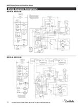
6000XL Series Service and Installation Manual REVISIONS REV DESCRIPTION DATE APPROVED 1 9294454 NOTES: 1) USE COPPER CONDUCTORS ONLY 2) THIS UNIT MUST BE GROUNDED 3) UNIT SHOWN WITH COMPRESSOR RUNNING AND DOORS CLOSED N LINE VOLTAGE 115/60/1 SEE NAMEPLATE FOR MAXIMUM FUSE SIZE L ENNIS M Y N 5 BLUE F M 6 FAN RELAY PLUG DEFROST HEATER EVAP COIL SENSOR CONTROL CIRCUIT W EVAPORATOR FAN INCANDESCENT LIGHT H 4 HEATER RELAY C M COMPRESSOR W WITH BLUE STRIPES W CONTROL BOX 1 COMPRESSOR RELAY ENERGY SAVER SWITCH 1 82 " W M SPLICE BLK CONDENSOR FAN CABINET AIR SENSOR EVAP COIL SENSOR WIRE NUT W P 1.1,2,3...
Open the catalog to page 10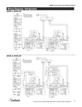
REVISIONS 6000XL Series Service and Installation Manual REV DESCRIPTION INITIAL RELEASE 1 DATE APPROVE 02-MAY-2011 L ENNIS 2 Wiring Diagrams: Refrigerators ADDED L-2/3 DESIGNATION & H-4 FOR HEATER TERMINAL 17-MAY-2011 L ENNIS 3 BROWN COMPRESSOR WIRE WAS BLACK (ON DIAGRAM ONLY) 26-MAY-2011 L ENNIS DATE APPROVE 11" 6076XL-S, 6076XL-SH 9294477 L1 NOTES: 1) USE COPPER CONDUCTORS ONLY 2) THIS UNIT MUST BE GROUNDED 3) UNIT SHOWN WITH COMPRESSOR RUNNING AND DOORS CLOSED N LINE VOLTAGE 115/60/1 SEE NAMEPLATE FOR MAXIMUM FUSE SIZE TEMPERATURE CONTROL L CONTROL CIRCUIT 2/3 RECEPTICAL BOX F FAN RELAY PLUG...
Open the catalog to page 11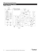
6000XL Series Service and Installation Manual Wiring Diagrams: Freezers LINE VOLTAGE FUSE SIZE HEATER RELAY DEFRDST HEATER 1) USE CDPPER CDNDUCTDRS DNLY 2) THIS UNIT MUST BE GRDUNDED 3) UNIT SHDVN WITH CDMPRESSDR RUNNING AND DDDRS CLDSEI EVAPORATOR HDUSING FRAME HEATERS For customer service, call (800) 733-8829, (800) 733-8821, Fax (888) 779-2040, www.delfield.com
Open the catalog to page 12All Delfield catalogs and technical brochures
 EcoMark Fabrication Solutions
12 Pages
 GURP-S technical sheet
2 Pages
 18600PTBMP technical sheet
4 Pages
 Chef Counters & Serving Systems
12 Pages
 4400 Series
28 Pages
 F16DD
F16DD2 Pages
 F5 & F15 SERIES
20 Pages
 Drop-Ins
8 Pages
 Standard Color Chart
1 Page
 Carts & Kiosks Product Guide
16 Pages
 UTSP
UTSP2 Pages
 Shelley Solution Systems
2 Pages
 Versa Drawer
8 Pages
 Coolscapes
4 Pages
 Mark 7 Custom Fabrication
16 Pages
 Global Reach-Ins
4 Pages
 ESP
ESP2 Pages
 Equipement Stands
4 Pages
 E-Chef
2 Pages
 Display Case
4 Pages
 DFN8200ST
2 Pages
 DF442712M
2 Pages
 DB4400
4 Pages
 Custom Fabricantion
8 Pages
 Concepts
8 Pages
 5415 Carts and Kiosk
8 Pages
 TT, TT2 Shelleymatic
2 Pages
 FT2-SN Shelleymatic
2 Pages
 CT Shelleymatic
2 Pages
 SSHRI-G series
2 Pages
 Pizza Prep Tables
6 Pages
 Specification Line®
4 Pages
 Shelley
8 Pages
 Convochill
12 Pages
 4427N-12M Mega Top
2 Pages
 6000XL? Reach-In
6 Pages
 F5 and F15 Series
20 Pages
 Compact Refrigerators & Freezers
16 Pages
 LiquiTec® Cold pans
4 Pages
 18600PTBM
4 Pages
 18PTB/18PTL/18PDL/F18 Series
5 Pages
 F13 Series
12 Pages
 Parts Catalog Fifth Edition
92 Pages


Archived catalogs
 Drop-Ins_2012
5 Pages
 Drop-Ins_2009
8 Pages
 Drawer system
2 Pages
 Service and Installation Manual
20 Pages
 Drop-Ins Product solution
9 Pages

- Commercial trolley
- Refrigerated display case
- Shop refrigerated display case
- Metal trolley
- Display case
- Refrigerated display case with light
- Contemporary display case
- Commercial display case
- Metal refrigerated display case
- Refrigerated display case with door
- Industrial office partition
- Standalone refrigerator
- Straight refrigerated display case
- Refrigerator-freezer
- Plastic trolley
- Metal refrigerator
- Home refrigerator
- Stainless steel refrigerated display case