 Website:
DAKOTA
Group: Dakota Group
Catalog excerpts
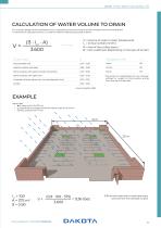
CALCULATION OF WATER VOLUME TO DRAIN For a correct design of the canalization line, it is essential to know the volume of the rainwater that has to be drained. To estimate an expected volume, it is used the Rational Method calculated as below V = Volume of water to drain (liter/second) Icr = Critical rainfall (mm/hr) A = Area of the surface (sqm) G = Flow coefficient (depending on the type of terrain) Asphalt surfaces well kept 0,85 + 0,90 Stone surfaces with good concrete connection 0,75 + 0,85 Stone surfaces with open joint 0,50 + 0,70 Unpaved surfaces, square rail, non-development land...
Open the catalog to page 3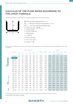
Drain | Flow Rate Calculation 2/3 The draining capacity for the above table were calculated according to the formula Chezy here below. Q = Channel Water Passage Section = H • L IItheorical = Perimeter Theorical Moistened Max = L + 2H nmeasured = Perimeter Measured Moistened Max R. = Radius Plumber = i measured if = Channel Slope X = Friction Coefficient V = Water Speed V = X /TR^fT Y = Bazin Coefficient X = 87 / (1 + ft/ V(Rj) ) ) Q = Scope = V • Q Once you know the water volume to drain you can choose the most appropriate channel, whereas the slope may be prepared during the phase of...
Open the catalog to page 4
Drain | Flow Rate Calculation 3/3 Drain | Flow Rate Calculation 3/3 The following table shows the flow for the PVC round pipe, with different diameters, depending on the installation slope. Scope Litres/second
Open the catalog to page 5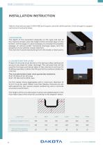
Drain | Installation Instruction Dakota channels are type M (EN 1433) and require concrete reinforcement, thick enough to support vertical and horizontal loads. 1. EXCAVATION The depth of the excavation depends on the type and size of the channel chosen, plus the height of the concrete layer on the bottom. At this stage, it is also necessary to consider the possible passage of vertical and/or horizontal drainage pipes, and the presence of any wells for waste collection. The channel must be laid starting from the lowest or drain point. 2. COCRETE BOTTOM LAYER A layer of concrete must be laid...
Open the catalog to page 6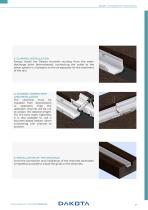
Drain | Installation Instruction 3. CHANNEL INSTALLATION Always install the Dakota channels starting from the water discharge point (downstream), connecting the outlet to the sewer system or, if present, to the oil separator for the treatment of the rain. 4. CHANNEL CONNECTION AND INSTALLATION The channels must be installed from downstream to upstream, then the upstream channel will be cut to obtain the desired length. For the best water tightness, it is also possible to use a bitumen-based sealant when connecting one channel to another. 5. INSTALLATION OF THE GRATINGS Once the connection...
Open the catalog to page 7
Drain | Installation Instruction 6. END-CAPS AND OUTLET On the upstream channel, insert the end-cap (sealing it with the same product used previously) and prepare the connection with the outlet. 7. PROTECTION OF THE GRATING It is essential to protect the grids already laid with a film or paper tape to avoid damage or scratches after the concrete itself has been poured. 8. CONCRETE FILLING Fill the trench with concrete, taking care to fill all the spaces. Use a finer-grained cement so that each groove is properly filled. Make sure that the level of the grating is at least 2mm lower than the...
Open the catalog to page 8
Drain | Installation Instruction TECHNICAL SITUATIONS WHERE A DRAINAGE CHANNEL IS REQUIRED The Dakota drainage channels are certified according to European legislation UNI EN 1433 which provides for a division in the following classes of load: Class A15 = 15 kN load test Group 1: Areas that can be used only by pedestrians and cyclists. Class B125 = 125 kN load test Group 2: Pedestrian paths, pedestrian areas and comparable areas, parking for private cars or multilevel car parks Class C250 = 250 kN load test Group 3: Road curbs and areas not directly exposed to vehicle traffic or similar;...
Open the catalog to page 9
Drain | Channel Installation INSTALLATION PICTURES
Open the catalog to page 10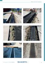
Drain | Channel Installation
Open the catalog to page 11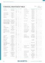
Drain | Material Properties CHEMICAL RESISTANCE TABLE legend: + resistant 0 partially resistant - not resistant Description Concentrations Temp. ° C PP HD-PE Acetic acid Technically pure, glacial Acetic aldehyde Acetic anhydride Technically pure Technically pure Technically pure Technically pure Description Cyclohexanone Ammonium fluoride Ammonium hydroxide Ammonium nitrate Ammonium sulphate Ammonium vinegar 50% aqueous Aqueous, saturated cold 10% aqueous 10% aqueous All, aqueous Antifreeze, liquid Aqua regia Aqueous boric acid Technically pure Technically pure Normal Concentration All,...
Open the catalog to page 12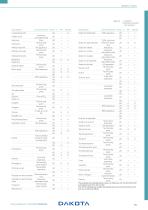
Concentrations Temp. ° C PP HD-PE 0 partially resistant - not resistant Concentrations Temp. ° C PP HD-PE Lubricating oils Maleic acid Mercury Methane Methyl alcohol Methyl chloride Metiletichetone Naphtha Naphtha Naphthalene Nitric acid Aqueous, saturated cold Pure Technically pure All, aqueous Technically pure Technically pure Sodium hydroxide 50% aqueous Sodium hypochlorite Sodium iodide Sodium nitrate Technically pure 40% aqueous Octylphtalate Oil Oleum Olive oil Technically pure Technically pure Sodium oxalate Sodium phosphate Sodium silicate Stearic acid Sulfuric acid 12,5% of active...
Open the catalog to page 13
DAKOTA DAKOTA GROUP S.A.S. REGISTERED OFFICE Via Pitagora, 3 37010 Affi, Verona - Italy OPERATIVE HEADQUARTER CONTACTS www.dakota.eu info@dakota.eu 37020 Brentino Belluno - Italy F. +39 045 6284075 VAT number: IT 07971400960 Register of Companies of Verona no. 07971400960 REA: VR-398568
Open the catalog to page 14All DAKOTA catalogs and technical brochures
-
STANDARD CATCH PIT
2 Pages
-
Gutter System
16 Pages
-
Channels & Gratings
28 Pages
-
Accessories for outdoor areas
16 Pages
-
Levelers and Spacers for Tiles
20 Pages
-
BUILDING
106 Pages
-
DRAIN
90 Pages
-
EQUIPMENT
26 Pages
-
INDOOR
60 Pages
-
OUTDOOR
96 Pages
-
ROOF
40 Pages
-
GLASS SHINGLES
1 Pages
-
LEVEL UP
12 Pages
-
Dakota Dakua
12 Pages


