- Catalogs
- CASAGRANDE - Foundation Division
- FD HYDROMILL
FD HYDROMILL
1 /18Pages

FD HYDROMILL
1 /18Pages
Catalog excerpts

The hydromills are designed by Casagrande to match today’s demands of diaphragm wall construction. Whenever the challenge of difficult soil condition, high productivity and shear accuracy are made in diaphragm walling, the Hydromills can cope. Versatility Whether in hard or soft soils, a choice of cutters is available to match every condition and demands of different wall width scan be easily met, simply by changing the cutter wheels and the interchangeable guides. All models of the hydromills are designed to work on the principle of reverse circulation. Cutting chains are used enable the equipment...
Open the catalog to page 2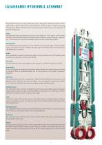
CASAGRANDE HYDROMILL ASSEMBLY The equipment consists of a heavy steel frame with two drive gears, attached to its lower section, which rotate in opposite directions around horizontal axes. The soil, or rock, is “milled” by the cutting wheels from the bottom of the trench and continuously moved, mixed with slurry, and removed by a powerful flushing pump. Frame Manufactured in heavy duty steel structure consists in the milling unit - lower section - which contains the motors, chain transmission system, excavating wheels and the slurry pump. The guide - upper section - which contains the control...
Open the catalog to page 4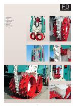
MILL’S BODY CHAIN STEERING PLATES CHAIN DETAIL MUD PUMP WHEELS SUCTION BOX
Open the catalog to page 5
CASAGRANDE HYDROMILLS FD60 The FD60 is the model that suits the widest range of requests for special foundations. A version is available with special motors to increase the wheels torque. The FD100 is designed with heavy duty wheel assembly and special hydraulic motors to deal with very thick diaphragms and under very demanding ground conditions. Length of trench mm Width of trench mm Torque al wheel axle kNm Wheel speed rpm Length of trench mm Width of trench mm Torque al wheel axle kNm Wheel speed rpm Suction pump md/h Verticality control wheels + n°2 steering plates Verticality...
Open the catalog to page 6
Crane The hydromill is suspended from the crane's winches, while the hydraulic hoses and debris pipe are supported by the two idler wheels activated by two independent tensioning systems. According to the length of the lattice boom, different excavation depth can be managed. Crane Hose Reels The hydromill is suspended from the crane's winches while two winders hold the hydraulic hoses and debris pipe. Each winder is activated by an independent hydraulic circuit in order to adjust the tensioning according to the depth to be dealt with. This configuration allows the reaching of considerable excavation...
Open the catalog to page 8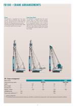
Crane The hydromill is suspended from the crane's winches, while the hydraulic hoses and debris pipe are supported by the two idler wheels activated by two independent tensioning systems. According to the length of the lattice boom, different excavation depth can be managed. Crane Hose Reels The hydromill is suspended from the crane's winches while two winders hold the hydraulic hoses and debris pipe. Each winder is activated by an independent hydraulic circuit in order to adjust the tensioning according to the depth to be dealt with. This configuration allows the reaching of considerable excavation...
Open the catalog to page 9
CUTTING TEETH FOR WHEELS AND CHAIN Type of teeth available According to ground characteristics, two typologies of cutting tools are available: – teeth for rock and hard rock – teeth soil and medium rock For their dimensions and sturdiness, teeth for hard rock are always suitable for mounting on the chain elements. HARD ROCK TEETH SOIL AND MEDIUM ROCK The teeth are arranged in such a way as to cover the entire excavation surface and to convey the excavated material towards the suction box. The position and inclination of each tooth assures the best cutting angle when in contact with the excavation...
Open the catalog to page 10
FULL EXCAVATION FACE The massive weight of the transmission motors and the lower blocks supporting the wheels concentrated in the lower part of the Hydromill frame, plus the utilization of the transmission chains’ system insure the distribution of the weight of the machine in the entire width of the excavation. The operator then, managing the “balance” of the weight of the rig will use the hydromill as a “reverse pendulum” system controls the verticality while optimizing production. The configuration of the wheels teeth together with the position of the chains’ teeth are designed to insure the...
Open the catalog to page 12
PANELS INSTALLATION HYDROMILLS 1. Pre-excavation (4-5 m) and excavation of primary panel 4. Installation of reinforcement and concreting 2. Excavation of second byte of primary panel 4. Excavation of secondary panel 3. Excavation of middle byte of primary panel 4. Installation of reinforcement and concreting
Open the catalog to page 13
Operator’s cabin The control instrumentation, installed in the operator’s cabin, allows checking of the correct operation of all basic machine functions and those of the hydromill. Over and above the basic machine controls, there is a simple panel of controls dedicated to hydromill control. 12” display The 12” colour touch screen display allows settings and provides information about the machine condition; moreover it allows and assists fault diagnostics. All machine functions are controlled by a PLC network. 3 Instrumentation The verticality of the hydromill is constantly monitored by the control...
Open the catalog to page 14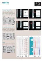
CONTROLS HYDROMILLS Verticality of the Hydromill All information on the orientation of the Hydromill and the deviation from the correct trajectory are shown on the control panel. The operator can correct the direction of excavation by using the controls of the steering plates. Each plate can assume four different positions. After having corrected the excavation trajectory, fully retract the guide plates. Verticality deviation along X-axis Feed - selection of speed and direction The load applied to the ground by the mills depend on ground conditions. The operator can control the feed (0-40 m/h)....
Open the catalog to page 15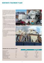
BENTONITE TREATMENT PLANT The desander plants are used to treat the slurries used for support in foundation engineering. The typical use is in excavation with hydromill or grabs in bentonite where the slurry from the excavation is treated in order to separate the soil from the bentonite. Some plant solutions are available depending of geological features and layout of the job site: • D500 plant has one cycloning stage and is suitable for slurry with rocks, gravels and sands. The D500 con be completed with one additional desilter plant with secondary cycloning stage and desilter dewatering screen...
Open the catalog to page 16All CASAGRANDE - Foundation Division catalogs and technical brochures
 C6T XP-2
8 Pages
 C20
C2012 Pages
 B125 XP
20 Pages
 B175 XP
24 Pages
 B200 XP
24 Pages
 B250 XP-2 – CFA Piling rig
24 Pages
 B275 XP-2 – CFA Piling rig
24 Pages
 B300 XP – CFA Piling rig
24 Pages
 B360 XP – CFA Piling rig
24 Pages
 KG25
KG2516 Pages
 KHD HYDRAULIC GRAB
12 Pages
 PM MECHANICAL GRAB
1 Page
 C5R XP-2
16 Pages
 C5 XP-2
16 Pages
 C6 XP-2
16 Pages
 C6-2
C6-216 Pages
 C7 XP
C7 XP16 Pages
 C8 XP-2
16 Pages
 C12 XP-2
16 Pages
 C9 XP
C9 XP16 Pages
 PG185
PG1858 Pages
 PILE DRIVER
8 Pages
 STONE COLUMNS
4 Pages
 KRC
KRC12 Pages
 C2 E
C2 E4 Pages
 C3 XP
C3 XP8 Pages
 C5 XP
C5 XP12 Pages
 C5S XP
8 Pages
 C6 XP
C6 XP16 Pages
 M9-1
M9-112 Pages
 C8 XP
C8 XP12 Pages
 C16 XP
4 Pages
 JET GROUTING
32 Pages
 C900 NG
6 Pages
 Cranes XP
12 Pages