
- Catalogs
- CARRIER commercial
- AERO® 39MN,MW03-110 Indoor and Weathertight Outdoor Air Handlers


AERO® 39MN,MW03-110 Indoor and Weathertight Outdoor Air Handlers

AERO® 39MN,MW03-110 Indoor and Weathertight Outdoor Air Handlers
- Protection and Installation: Units are shrink-wrapped for transit protection and feature factory-supplied variable frequency drives. They are easy to assemble with minimal tools.
- Design and Flexibility: Stacked configurations and non-staggered coils reduce footprint and allow for versatile application. Accessibility from one side increases location options.
- Durability: Double-wall R-13 insulation prevents exposure to the airstream, and internally mounted motors extend the life of components.
- Performance Optimization: AHUBuilder software aids in unit selection and performance optimization, offering various fan options and coil selections.
- Indoor Air Quality (IAQ): Multiple filtration options and UV-C germicidal lamps improve air quality and reduce maintenance needs.
- Coils: A variety of coil types are available, including chilled water, direct expansion, hot water, and steam coils, each designed for specific applications and efficiency.
- Face and Bypass Coils: Integral face and bypass coils maintain constant air volume and temperature, ensuring efficient mixing and temperature control.
- Customization: Options for air mixers, direct digital controls, and custom design enhancements are available to meet specific application needs.
- AgION Antimicrobial Coating: Provides long-term protection against microbial growth by releasing silver ions in humid conditions.
- Energy and Maintenance Savings: UV-C lamps reduce energy costs and maintenance needs while improving indoor air quality.
1. Thermostat: The indoor unit operates with its own thermostat.
2. High Filtration Units: These units have a filter section before the cooling and heating coils and a final filter at the air entry point into the ductwork.
3. Fans: The 39M central station air handlers use belt-driven centrifugal fans, which can be double width, double inlet (DWDI) with forward curved or airfoil blades, or single width, single inlet (SWSI) with airfoil blades.
Fan performance is predicted using fan laws, which relate variables such as airflow (CFM), rotational speed (RPM), pressure (P), horsepower (Hp), fan wheel diameter (D), and air density (W). These laws apply to geometrically similar fans and include:
- Airflow varies directly with speed.
- Pressure varies as the square of speed.
- Horsepower varies as the cube of speed.
- Capacity and horsepower vary as the square of fan size.
- Speed varies inversely as fan size.
- Pressure remains constant with fan size changes.
1. System Requirements: Factors include airflow, static pressure, fan speed, brake horsepower, and sound level.
2. Pressure Considerations: Static pressure is the resistance of the system, influenced by components like ductwork and terminals. It varies as the square of airflow.
3. Stability: Fan operation should remain stable after disturbances. Instability can lead to system surge or fan stall.
4. Sound Considerations: Fans are major sound sources. Correct sizing and selection can minimize sound levels, especially in VAV systems.
When selecting fans for systems with dirty filters, consider:
- Adjusting fan selection for clean filter RPM but using motor horsepower for dirty filters.
- Using airfoil fans to minimize differences between clean and dirty airflow.
Fan, motor, and drive heat contribute to airflow and pressure. Efficiency losses translate into heat, affecting power requirements and cooling/heating loads. Calculations for motor output and heat output are necessary to ensure proper sizing and performance.
1. Forward-Curved Fans: Suitable for low to medium pressure applications, stable over a wide airflow range, and have the lowest first cost.
2. Airfoil Fans: Efficient at higher static pressures, with bhp decreasing as air volume decreases when using VAV devices.
3. Plenum Fans: Used in medium to high static pressure applications where discharge location flexibility is needed.
- Headers: Distribute heating or cooling medium to tubes, typically made of non-ferrous metal or steel.
- Casing: Supports tubes and headers, usually made of galvanized or stainless steel.
- Inlet and Outlet: Pipe stubs on the header for medium entry and exit, with specific arrangements for water and steam coils.
- Finned Area: The working area of the coil, defined by the width and length through which air passes.
- Cooling Coils: Available in various row configurations, with specific tube diameters for optimal heat transfer.
- Direct Expansion (DX) Coils: Feature multiple circuiting options for performance optimization.
1. Unit Size Calculation: The coil face area is determined by dividing the design CFM by the maximum face velocity. For example, 12,000 CFM divided by 500 FPM results in a size of 24, rounded to Size 25.
2. Component Selection: Choose appropriate component sections based on the system requirements.
3. Dimensions and Weight: Determine the overall unit dimensions and weight. The height and width remain consistent across component sections for a given unit size.
4. Final Selection: Use Carrier’s AHUBuilder® program for finalizing selections, which aids in efficient air handler choice.
Minimum Face Area: Calculated as 3,000/650 FPM = 4.6 sq ft.
Actual Face Velocity: 3,000/4.9 sq ft = 615 FPM.
Heating Load: 75.9 MBtuh/3.413 MBtuh/kW = 22.2 kW.
Capacity: 23 kW x 3.413 = 78.5 MBtuh.
Air Temperature Rise: 78,500 Btuh/(1.1 x 3,000 CFM) = 23.8°F.
Leaving Air Temperature: 54°F + 23.8°F = 77.8°F.
Voltage variations affect the electric heating coil’s output, calculated using the formula: kWa = kWr x (Va/Vr)^2, where kWa is the actual kW output, kWr is the rated kW output, Va is the actual voltage, and Vr is the rated voltage.
Filter Pressure Drop: Data provided for clean filters, with typical allowances for dirty filters ranging from 0.5 to 2.5 in. wg depending on the filter type.
Component Pressure Drop: Includes data for mixing box dampers, diffuser plates, and various coil air frictions.
Control Steps: Standard control steps are listed, with additional steps available for more subcircuits.
Notes: Subcircuits are internal heater circuits of 48 amps or less. Electric heat performance is not within AHRI standard 430 certification. Minimum face velocity must not fall below 350 FPM to avoid overheating damage. Heaters up to 60 kW have 3 control steps; beyond 60 kW, 6 steps are standard.
Top intake is not available on 39MW outdoor units. Mixing boxes feature double-wall, insulated, galvanized steel floors with various accessibility options including hinged double-wall access doors or removable panels. Exhaust boxes also have double-wall, insulated, galvanized steel floors with similar accessibility options.
Factory-Installed Options
Thermal pane reinforced glass viewports and marine lights are available as factory-installed options for mixing box sections.
Dampers
Mixing and exhaust boxes are equipped with parallel or opposed blades and interconnecting outside-air and return-air dampers. Standard dampers are made of galvanized steel with blade seals and stainless steel jamb seals, with a maximum leakage rate of 4 cfm/ft² at 1 in. wg. Premium dampers have a double-skin airfoil design with a maximum leakage rate of 2 cfm/ft².
Dimensions and Weight
The document provides detailed dimensions and weights for both indoor (39MN) and outdoor (39MW) units across various sizes. Dimensions include height (H), width (W), airway length (AWL), duct depth (DA), and duct width (DW).
Filtration
Filter mixing boxes accept 2-in. or 4-in. filters with side access slide rails. Angle filter sections are arranged in a horizontal V formation.
Air Mixer
Constructed of .081-in. aluminum, the air mixer is designed to mix air streams of differing temperatures to within ±6°F of the theoretical mixed-air temperature, ensuring uniform air velocity entering downstream filters or coil banks.
Coil Sections
All coil sections are of solid double-wall construction with galvanized steel inner and outer panels, carrying an R-value of no less than 13. They include removable frame sections for vertical coil extraction.
The document outlines specifications for various filter and coil sections used in HVAC systems. It includes details on dimensions, weight, and filter sizes for both indoor and outdoor units.
Filter Sections
- Draw-thru Bag/Cartridge Filter Sections: Capable of accepting 6-in. to 12-in. deep rigid media or bag filters. Accessibility options include hinged double-wall access doors or removable panels.
- Horizontal, Short Bag/Side Loading Cartridge Filter Section: Dimensions and weight vary by unit size, with specific filter sizes and face areas provided.
- Blow-thru Bag/Cartridge Filter Sections: Designed for face loading filter frames, accepting 12-in. deep rigid media or bag filters. Optional thermal pane reinforced glass viewports available.
- Blow-thru HEPA Filter Sections: Accepts 12-in. deep HEPA box filters with similar accessibility options as other sections.
Coil Sections
- Cooling Coil Section with Drain Pan: Features solid double-wall construction with insulation, removable frame sections, and sloped drain pans complying with ASHRAE Standard 62.
- Extended Length Cooling Coil Section: Similar construction and specifications as the standard cooling coil section, with extended length options.
- Heating Coil Section: Offers large, medium, and bypass coil face areas, with similar construction and accessibility options as cooling sections.
- Extended Length Heating Coil Section: Provides extended length options with the same construction standards.
- Dual Coil Section with Drain Pan: Includes large and medium coil face areas, with detailed specifications on construction and drainage.
General Construction and Accessibility
All sections are constructed with solid double-wall galvanized steel, ensuring a minimum R-value of 13. Accessibility is facilitated through hinged or removable double-wall access doors and panels.
The document outlines the construction and specifications of electric heater casings and coil sections. The electric heater casing is made of galvanized steel, with coil sections featuring solid double-wall construction and insulation sealed between panels. The heater control box is accessible from the designated side of the unit. There are two types of element constructions: open-wire and sheathed, both using 80% nickel and 20% chromium resistance coils. These elements are designed to meet UL and NEC requirements, with a maximum heating density of 55 watts/sq inch. The units are UL listed for zero clearance and comply with the National Electric Code and UL 1995 Standard for Safety.
Dimensions and Weight:
The document provides detailed dimensions and weights for both indoor (39MN) and outdoor (39MW) unit sizes, ranging from size 03 to 110. Dimensions include height (H), width (W), and airway length (AWL), with weights specified in pounds. The dimensions are crucial for installation and space planning.
Heat Transfer Sections:
These sections are constructed with solid double-wall galvanized steel, ensuring durability and insulation. The document specifies the availability of multizone/dual duct heating/cooling coil sections with drain pans, which are not available for outdoor units. The coil sections have removable frame sections for easy maintenance and comply with ASHRAE Standard 62 for drainage.
Fan Motor Sections:
The fan motor sections include horizontal draw-thru, horizontal blow-thru, and vertical draw-thru supply fans. Each section has specific dimensions and weights, with options for accessibility through hinged or removable double-wall access panels. The fan sections are designed with a double-wall, insulated, galvanized steel floor, and options for thermal pane reinforced glass viewports and marine lights.
Key Features and Options:
- Double-wall construction for enhanced insulation and durability.
- Compliance with UL, NEC, and ASHRAE standards.
- Accessibility options for maintenance and inspection.
- Detailed specifications for fan and coil sections, including dimensions and weights.
- Options for thermal pane viewports and marine lights for enhanced functionality.
The document outlines specifications for fan motor sections, including options for thermal pane reinforced glass viewports and marine lights as factory-installed options. It specifies that fan supports and structural members should not be welded unless made from corrosion-resistant materials. The fan section features a double-wall, insulated, galvanized steel floor with various accessibility options.
Fan Dimensions and Weights
The document provides detailed dimensions and weights for both indoor and outdoor units across various sizes (03 to 110). It includes measurements for height, width, airway length, and weight for Forward Curved (FC) and Airfoil (AF) fans.
Fan Offerings by Unit Size and Type
Details are provided for Forward Curve, Airfoil, and Plenum fans, including maximum and minimum horsepower and frame sizes for supply and return/exhaust fans across different unit sizes.
Fan Data by Wheel Diameter and Type
The document includes data on fan wheel diameters, inlet cone diameters, maximum speeds, fan shaft diameters, fan wheel weights, and the number of fan blades for Forward Curve, Airfoil, and Plenum fans.
Key Recommendations
Consult AHUBuilder® for exact dimensions as fan diameters or discharge locations may affect airway lengths. Guide specifications for fan detail options are available on pages 80-107.
The document outlines the specifications for 39M Central Station Air Handler Units, focusing on quality assurance, delivery, storage, protection, and start-up requirements. The units must be manufactured in ISO 9001 certified facilities and meet UL 1995 safety standards. They should also comply with AHRI and NFPA standards.
Quality Assurance:
The manufacturer must have at least five years of experience. Units should be UL 1995 certified and listed by ETL and CSA. Coil performance must adhere to AHRI Standard 410.
Delivery and Storage:
Units must be shrink-wrapped for protection during shipment. They should be inspected for damage and stored in a clean, dry place.
Start-Up Requirements:
Units should not be operated until all components are verified and tested, including ductwork, filters, bearings, and piping connections.
Product Description:
Units are shipped in sections or assembled, with various factory-installed components like mixing boxes, air mixers, exhaust boxes, and coil sections. Options include different filter types and coil configurations.
Casing Construction:
The casing must be thermally broken and constructed of galvanized steel with specific finishes. Panels should be double-wall with insulation, and deflection and leakage rates must meet specified standards.
Fans:
Fans are designed for continuous operation and must meet AMCA class ratings. They should be dynamically balanced and mounted on a common base assembly with isolators.
Bearings and Drives:
Bearings must be self-aligning and grease-lubricated, with extended lubrication fittings. Shafts should be solid steel, and V-belt drives must have a minimum service factor.
Coils:
Coils must meet AHRI Standard 410 and be tested at 450 psig air pressure. They should be constructed with copper tubes and aluminum or copper fins, with optional specifications available.
- Headers and Nipples: US headers and red brass nipples are optional. Coils must be drainable and suitable for a design working pressure of 300 psig at 200°F.
- Steam Distribution Heating Coils: Steel headers with MPT connections. Inner steam distributing tubes are specified with dimensions and working pressure of 175 psig at 400°F.
- Integral Face and Bypass Coils: Horizontal and vertical steam or hot water coils with specified tube wall thickness and construction details.
- Refrigerant Coils: Copper headers with brazed joints, various circuiting selections, and replaceable nozzle brass refrigerant distributors.
- Electric Heating Section: Galvanized steel construction with specific element types, thermal cutouts, and UL listing requirements.
- Direct discharge type using steam from existing lines. Constructed with 316 stainless steel and designed for optimal steam to air contact.
- Features include full-length inverted slots for steam discharge, stainless steel baffles, and insulative coatings to reduce surface temperature.
- Various configurations for flat, angle, draw-thru, and blow-thru filter sections, capable of accepting different filter sizes and types.
- Magnehelic gauges with specified construction, accuracy, and pressure limits.
- Mixing boxes and exhaust boxes with parallel or opposed blades. Specifications for standard, premium, and outside air measurement dampers.
- Integral face and bypass dampers designed for constant air volume and temperature control.
- Constructed of aluminum, designed to mix air streams to a specified temperature range and provide uniform air velocity.
- Designed for HVAC systems with specified output intensity and power supply requirements. Fixtures are factory installed with safety features.
- Marine lights and convenience outlets with weatherproof construction and UL listing.
- Disconnects with specified characteristics for single-phase and three-phase applications.
- 240 VAC Disconnects: Features include visible blades, quick-make/quick-break mechanism, padlock provisions, 240 VAC maximum, factory-installed Class RK5 fuses, up to 100,000 RMS symmetrical amperes SCCR, horsepower rated, tangential knockouts, spring-reinforced copper fuse clips, NEMA Type 1 enclosures, insulated neutral assemblies, UL listed, and compliance with NEMA KS1-1990.
- 380-575 Volt/3-Phase Disconnects: Characteristics include visible switch blades, quick-make/quick-break mechanism, dual cover interlock, color-coded indicators, padlock provisions, 600 VAC maximum, factory-installed Class RK5 fuses, up to 200,000 RMS symmetrical amperes SCCR, horsepower rated, tangential knockouts, NEMA Type 1 enclosures, insulated neutral assemblies, suitable wire terminations, UL listed, and compliance with NEMA KS1-1999.
- Starter without Disconnect: Includes adjustable motor overload, manual reset button, 115V fused control transformer, Hand/Off/Auto switch, terminal strip for remote wiring, C series contactors, horsepower rated, NEMA 4X enclosures, lug connections, factory tested, and UL listed.
- Combination Starter/Disconnect: Features a non-fused UL 508 disconnect switch, cover interlock, adjustable motor overload, manual reset button, 115V fused control transformer, Hand/Off/Auto switch, terminal strip for remote wiring, C series contactors, horsepower rated, NEMA 4X enclosures, lug connections, factory tested, and UL listed.
- 200-230 V/3 Ph/60 Hz and 460-575 V/3 Ph/60 Hz: Includes a 4-position disconnect switch, switch position indication, adjustable motor overload, manual reset button, horsepower rated, direct control, complete inverter isolation, NEMA 12 enclosures, terminal strip for wiring, lug connection for ground wire, auxiliary switch contact set, factory tested, and UL, Canada, CE listed.
- Factory-mounted and wired to motors, programmed for a 24-month warranty, parameters stored in a removable keypad, UL listed enclosures, capable of operating in various environmental conditions, and include standard features such as digital display, keypad, timeclock, application macros, cooling fans, flying start capability, automatic restart, overload rating, internal impedance reactors, transient surge protection, loss-of-load relay output, user programmable functions, and multiple PID algorithms.
- Adjustments include critical frequency lockout, PID set point controllers, independent PID loop, programmable analog inputs and outputs, digital inputs, Form-C relay outputs, run permissive circuit, programmable start delay, preset speeds, adjustable ramps, and motor flux optimization.
The document outlines the specifications for a Variable Frequency Drive (VFD) system designed to optimize motor noise, energy consumption, and speed control. Key features include a carrier frequency control circuit that adjusts based on VFD temperature, password protection for parameter changes, and a backlit LCD display for programming and diagnostics in English.
Keypad and Display:
The keypad includes a minimum of 14 assistants for various functions such as start-up, parameter adjustments, and troubleshooting. The display can show at least three operating values like output frequency, motor speed, and motor power in user units.
Fireman’s Override:
The VFD includes a fireman’s override input that allows operation at a fixed speed or through a specific PID algorithm during emergencies, overriding other inputs except safety interlocks.
Serial Communications:
The VFD supports multiple protocols including Modbus and BACnet, with certified connections. It allows for extensive monitoring and control capabilities, including remote fault reset and independent PID loops.
EMI/RFI Filters:
All VFDs include filters to meet EN 61800-3 standards, ensuring compliance with CE marking requirements.
Protection and Operational Functions:
The VFD is protected against power mis-wiring and includes features like adjustable acceleration/deceleration times, preset speeds, and soft stall capabilities. It also supports custom user settings and pattern runs.
Protective Features:
The drive is rated for high interrupting capacity and includes alarms for various conditions like over-torque and communication errors. It can display numerous fault conditions for diagnostics.
Monitor Functions:
The drive can display various operational parameters and includes a large number of programmable parameters accessible via touchpad or computer link.
Quality Assurance:
The document specifies manufacturing standards, including ISO 9001 certification and compliance with UL and AHRI standards.
Delivery and Start-Up:
Guidelines for delivery, storage, and start-up are provided to ensure proper handling and operation of the units.
Product Description:
The air-handling units are described with options for various sections like mixing boxes, coil sections, and fan sections. Construction details include casing materials, insulation, and structural integrity requirements.
1. Accessibility options include hinged double-wall access doors and removable panels, with thermal pane reinforced glass viewports and marine lights as optional features.
2. Fan supports and structural members should not be welded unless made of corrosion-resistant materials.
3. Coil sections must have solid double-wall construction with a minimum R-value of 13.
4. Blow-thru fan sections require an integral diffuser plate.
Access Doors:
Access doors should be double-wall with insulation, maintaining an R-value of at least 13.
Drain Pans:
Drain pans must be insulated, sloped, and comply with ASHRAE Standard 62, ensuring no standing water.
Roof Curbs:
1. Delivered unassembled, constructed of 14-gage galvanized steel.
2. Include wood nailers and channel supports for curbs over 10 ft.
Hoods and Louvers:
1. Outside air hoods made of 20-gage galvanized steel with moisture eliminators.
2. Exhaust air hoods include bird screens.
3. Side intake louvers designed to withstand wind loads and minimize water penetration.
Fans:
1. Fans constructed of galvanized steel, designed for continuous operation, and dynamically balanced.
2. Airfoil and plenum fans have specific construction and balancing requirements.
3. Fan motors must be premium efficiency and comply with EISA 2007.
Bearings and Drives:
1. Bearings are self-aligning and grease lubricated, with options for extended life.
2. Shafts are solid steel, coated for rust prevention.
3. V-belt drives designed with a minimum service factor.
Coils:
1. Coils must meet AHRI Standard 410 and be tested at specified pressures.
2. Construction includes copper tubes and aluminum or copper fins.
3. Hydronic and steam coils have specific configurations and pressure ratings.
Electric Heating Section:
1. Constructed of galvanized steel with open-wire or sheathed elements.
2. Includes thermal cutouts and meets UL and NEC requirements.
Humidifiers:
1. Direct discharge type using steam, constructed of 316 stainless steel.
2. Designed for optimal steam to air contact with minimal pressure drop.
The steam humidifier is designed for easy assembly with slip fittings and requires no maintenance due to the absence of plastic components. It includes a non-toxic insulative coating to reduce surface temperature and heat gain, with a high insulating value and low flame spread rating.
Filter Sections:
Various filter sections are available, including flat, angle, draw-thru, and blow-thru configurations, capable of accommodating different filter sizes and types. Magnehelic gauges are used for pressure measurement, featuring durable construction and high accuracy.
Dampers:
Mixing boxes and exhaust boxes include standard, premium, and outside air measurement dampers, constructed with galvanized steel and designed for minimal leakage. Integral and internal face and bypass dampers maintain constant air volume and temperature, with options for field-mounted actuators.
Air Mixer:
The air mixer is constructed from aluminum and designed to mix airstreams of differing temperatures to achieve a uniform air velocity and temperature.
UV-C Germicidal Lamps:
Designed for HVAC systems, these lamps provide UV-C energy to maintain coil and drain pan cleanliness. They are factory-installed with high-efficiency power supplies and ensure even distribution of UV-C energy.
Electrical Accessories:
Includes marine lights, convenience outlets, and various types of disconnects and starters. These components are designed for durability, safety, and ease of use, with features like weatherproof enclosures and UL listings.
Variable Frequency Drives (VFDs):
Factory-mounted VFDs are pre-programmed and tested, offering a warranty and easy replacement process. They are designed to be shielded from upstream components and maintain optimal performance.
The Variable Frequency Drive (VFD) package must be enclosed in a UL Listed type enclosure, surpassing NEMA design criteria, and assembled in an ISO 9001 facility. It should operate within a voltage range of +30% to -35% nominal and withstand environmental conditions from 0 to 50°C and altitudes up to 3300 feet with less than 95% humidity. All circuit boards require conformal coating.
Standard Features:
All VFDs must have a consistent customer interface with a digital display and keypad, which is removable and capable of remote mounting. The keypad should support Hand-Off-Auto selections, manual speed control, and include a built-in timeclock with a 10-year battery backup. The VFD should support pre-programmed application macros, easy replacement of cooling fans, and a flying start capability. It must also automatically restart after protective trips and have an overload rating of 110% for 1 minute every 10 minutes.
Protection and Control:
The VFD should include internal 5% impedance reactors for harmonic reduction and transient protection, a coordinated AC transient surge protection system, and programmable loss-of-load detection. It should support multiple PID algorithms for dual feedback control and offer options for input reference loss response.
Adjustments and Interfaces:
VFDs should have programmable critical frequency lockout ranges, PID set point controllers, and multiple programmable analog and digital inputs/outputs. It should include a run permissive circuit, programmable start delay, and motor flux optimization for energy efficiency. Password protection for parameter changes is required.
Display and Diagnostics:
The keypad must feature a backlit LCD display with complete English words for programming and diagnostics. It should include various assistants for start-up, parameter setting, and troubleshooting.
Fireman’s Override and Serial Communications:
The VFD must have a fireman’s override input and support standard protocols like Modbus and BACnet, with optional protocols available. It should allow comprehensive serial communication capabilities for control and monitoring.
EMI/RFI Filters:
All VFDs must include EMI/RFI filters to meet CE Marking and EN 61800-3 standards for the First Environment restricted level.
The document specifies that motor cables can be up to 100 feet with no exceptions, and certified test reports must confirm compliance with EN 61800-3, First Environment. All Variable Frequency Drives (VFDs) up to 75 hp at 480 V must be protected from input and output power mis-wiring, with alarms displayed on the keypad without sustaining damage.
Operational Functions:
The VFDs should have two separate acceleration/deceleration times with auto-tuning, local/remote and manual/auto keys, a quick setup key, 15 preset speeds, and the capability to store custom user settings. They should restart into a rotating motor, have adjustable soft stall, perform time-based pattern runs, and have adjustable electronic overload protection. Custom programmable volt/hertz patterns are also required.
Protective Features:
The drive must be rated for 200,000 AIC without input fuses, have external fault input, and be capable of resetting faults remotely and locally. It should alert various alarms such as over torque, inverter overload, motor overload, and more. The drive should identify and display faults like overcurrent, overvoltage, inverter overload, and communication errors.
Monitor Functions:
The drive's digital display should show frequency, current, voltage, RPM, and more. It should have 320 programmable parameters, adjustable from an 8-key touchpad or computer link, and be NEMA 12 rated. The keypad can be extended 15 ft from the drive. The drive should reset parameters to factory or user defaults, have programmable analog and relay outputs, digital inputs, a pulse train output, and an elapsed time meter.
Manufacturer's Note:
The manufacturer reserves the right to change specifications or designs without notice.
Catalog excerpts

AERO® 39MN,MW03-110 Indoor and Weathertight Outdoor Air Handlers Product Data 1,500 to 60,500 Nominal Cfm A39-4249 39MN INDOOR UNIT A39-4250 Carrier’s 39M air handlers offer: • Units are shrink wrapped for complete protection while in transit • Factory-supplied variable frequency drives that are programmed and started up at the factory • Sealed panel double-wall R-13 insulation system • Stacked indoor unit configurations for application versatility and maximum space utilization • Outdoor weathertight cabinets have sloped roofs to prevent standing water, and are gasketed in all critical areas. • Factory-installed integral face and bypass coils for extreme conditions • Factory-installed humidifiers for precise indoor climate conditioning • Available factory-mounted controls, starters, disconnects and variable frequency drives • AHUBuilder® software for easy unit selection • Optional prepainted unit exterior • Optional AgION® anti-microbial coated panel interior • Optional factory-installed UV-C germicidal lamps Features/Benefits The Aero 39M air handler is the only unit on the market that practically installs itself. Easy installation 39MW OUTDOOR UNIT Copyright 2010 Carrier Corporation Frames, corners and base rails of the 39M air handler are all easily disassembled and reassembled in minutes with as little as 3 standard tools. Carrier’s 39M units can be ordered with shipping splits, which speed section to section assembly. All panels are easily removed in one piece for cleaning or access to components. Form 39M-11PD
Open the catalog to page 1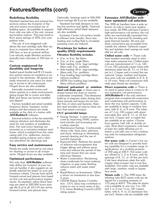
Features/Benefits (cont) Redefining flexibility Standard stacked fans and exhaust box sections reduce the footprint of the unit and ensure economical use of building space. Accessibility is required from only one side of the unit, increasing location options. This may result in floor space savings of 20% over competitive units. The use of non-staggered coils allows flat and cartridge style filter sections to maintain face velocities of 500 fpm or less at nominal airflow. Low velocity angle filtration sections typically have velocities of 350 fpm or less. Custom engineered for durability and longevity...
Open the catalog to page 2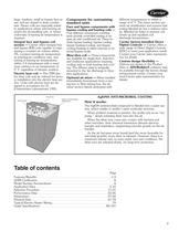
large, medium, small or bypass face areas, and are sloped to drain condensate. Steam coils are especially suited to applications where sub-freezing air enters the air-handling unit, or where uniformity of leaving-air temperature is required. Integral face and bypass coil section — Carrier offers integral face and bypass (IFB) coils capable of maintaining a constant air volume within 5%, constant leaving-air temperature as entering-air conditions vary, and mixing of leaving-air temperatures within 3 ft downstream with a maximum variance in air temperature of 5° F, regardless of damper position....
Open the catalog to page 3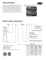
AHRI certification Carrier 39 Series air handler units are rated and certified in accordance with AHRI Standard 430, which is the industry standard for central station air-handling units. Certification by participating manufacturers of units within the scope of this program requires that the ratings and performance of any central station unit certified to AHRI be established in accordance with the AHRI Standard. Coils installed in the Carrier 39 Series air handler units are rated and certified in accordance with AHRI Standard 410. Plenum fans are rated in accordance with Air Movement and Control...
Open the catalog to page 4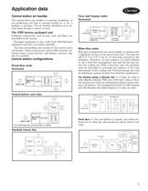
Application data Central station air handler Face and bypass units The central station air handler is a heating, ventilating, or air-conditioning unit that is centrally located in, or on, a building or structure. The air handler distributes air to desired areas through a system of ducts. Horizontal The 39M factory packaged unit Individual components, such as fans, coils, and filters, are assembled at the factory. Packaged equipment is less costly than field-fabricated equipment and does not require assembly. The basic air-handling unit consists of a fan section and a coil section. Other components,...
Open the catalog to page 5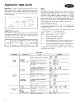
Application data (cont) Multizone — Mixing dampers blend hot-deck and colddeck temperatures to produce a desired temperature for individual zones. Several blending dampers per unit produce independent zones, each responding to its own thermostat (indoor unit only). ZONING DAMPERS FILTER PLENUM FAN HEAT AIRFLOW COOL A39-4028.eps MIXING BOX High filtration units MIXING BOX FILTER AIRFLOW COOL High filtration units employ a filter section ahead of the cooling and heating coils. A second filter section, called a final filter, is placed at the end of the unit at the point where the air enters the...
Open the catalog to page 6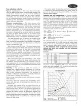
Fan selection criteria System requirements — The major factors that influence fan selection are airflow, external static pressure, fan speed, brake horsepower, and sound level. Additional system considerations include the fan control method, overloading, and non-standard air density. Fan selection for air-conditioning service usually involves choosing the smallest fan that provides an acceptable level of performance, efficiency and quality. Pressure considerations — The static pressure is the resistance of the combined system apart from the fan. Contributors to static pressure include other components...
Open the catalog to page 7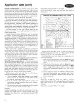
Application data (cont) 8 Clean filters result in a TSP of 2.55 inches. In the chart below, follow the 1010 rpm line down to 2.55 inches. 39M SIZE 30 FORWARD-CURVED FAN CURVE 8 MSE 7 SC 6 TOTAL IN. WG Sound considerations — The fan is one of the main sound sources in an air-conditioning system. Other sources of sound include the duct system and terminals, because they generate turbulence in the air flowing through them. Simply estimating fan sound does not give an accurate picture of total system sound, but fan sound is a major component of system sound, and should be minimized. To minimize its...
Open the catalog to page 8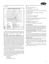
In the chart below, follow the 2210 rpm line down to 2.55 inches. 39M SIZE 30 AIRFOIL FAN CURVE 11 MSE 10 SC 9 TOTAL IN. WG 8 7 6 4 RP 3 2 1 0 2 4 6 8 10 12 14 16 18 20 22 24 26 28 AIRFLOW (1000 CFM) LEGEND \ \ Calculate the total fan motor heat output (Q) according to motor efficiency: Q = (Motor Output) ÷ (Motor Efficiency [Typical]) Q = 9.89 ÷ 0.86 Q = 11.5 hp Convert horsepower to Btu per hour. 11.5 hp x 2545 = 29,268 Btuh 5 0 Calculate the required fan motor output (Hp) due to drive loss. Hp = (Fan bhp) x (Drive Loss) Hp = 9.6 x 1.03 Hp = 9.89 hp (select 10 Hp motor) — Rpm — Bhp (Brake Horsepower)...
Open the catalog to page 9All CARRIER commercial catalogs and technical brochures
 A WORLD OF COMFORT PRINT
10 Pages
 A WORLD OF COMFORT (2025)
20 Pages
 19DV
19DV32 Pages
 30XA
30XA136 Pages
 30RAP
30RAP104 Pages
Archived catalogs
 AirStream™ Room Fan Coils
4 Pages
 42B-6SI
24 Pages
 40UV-UH-14SI
32 Pages
 The CRRSA Act (ESSER I)
2 Pages
 AERO® Air-Handling Units
4 Pages
 Axis™ Overhead Air Terminals
4 Pages
 Carrier-Catalogue-2018-2019
940 Pages
 2019 Carrier Ductless
88 Pages
 Carrier VRF
44 Pages
 Axis Overhead Air Terminals
2 Pages
 Roomtop® 50AH036-072
24 Pages
 OMNIZONE™ 50BV020-064
64 Pages
 A World of Comfort 2015
2 Pages
 Low Noise Type CABINET FAN
16 Pages
 Performance 16 Heat Pump
4 Pages
 ComfortVIEW 3
6 Pages
 VVT Zoning System
8 Pages
 Heat Reclaim Chillers
2 Pages
 Airstream Unit Ventilators
2 Pages
 Airstream Room Fan Coils
2 Pages
 Aero Air-Handling Units
2 Pages
 17DA Centrifugal Chiller
2 Pages
 AXIS? Overhead Air Terminals
3 Pages
 Comfort? Series
2 Pages
 GEMINI? 38AKS028-044
40 Pages
 i-Vu Open Standard & Plus
2 Pages
 A World of Comfort
2 Pages
 AIRSTREAM™ Room Fan Coils
3 Pages
 ROOMAIR CONDITIONERS
6 Pages
 Water-Cooled Chillers
3 Pages
 Antimicrobial Solutions
3 Pages


- CARRIER heat pump
- CARRIER residential heat pump
- CARRIER air conditioner
- CARRIER air source heat pump
- CARRIER surface-mounted detector
- CARRIER outdoor heat pump
- White thermostat
- Mechanical ventilation unit
- CARRIER white detector
- CARRIER programmable thermostat
- Commercial air conditioning cabinet
- Heating thermostat
- CARRIER digital thermostat
- CARRIER commercial detector
- Split air conditioning unit
- CARRIER wall-mounted thermostat
- Inverter heat pump
- Reversible air conditioner
- Thermostat with digital display