
- Catalogs
- CARRIER commercial
- 45X, 45U, 42K, 35BF Axis Access Floor Terminal Units for Variable Air Volume Systems


45X, 45U, 42K, 35BF Axis Access Floor Terminal Units for Variable Air Volume Systems

45X, 45U, 42K, 35BF Axis Access Floor Terminal Units for Variable Air Volume Systems
Carrier's Axis Underfloor HVAC Systems provide flexibility and economic advantages for commercial office buildings by integrating HVAC air distribution with power and communication wiring within a raised floor plenum. Key benefits include:
- Flexibility for workplace changes with easy diffuser relocation and accessible cabling.
- Reduced installation costs due to smaller fans and elimination of ductwork.
- Lower operating costs with efficient airflow patterns and demand control ventilation.
- Improved air quality with direct fresh air supply and individual temperature control.
The document details various Carrier products for underfloor HVAC applications:
- 45X Fan Powered Zone Mixing Unit: Controls air pressure and temperature, offering a range of 50 to 6200 cfm. Features include factory-mounted controls, ECM motors, and sound ratings compliant with ARI standards.
- 45U Underfloor Series Flow Fan Powered Unit: Fits between floor grid pedestals, suitable for high interior loads and perimeter applications.
- 42K Perimeter Fan Coil Unit: Provides heating to perimeter zones, drawing air from the plenum.
- 35BF-R High Induction Swirl Diffuser: Allows for individual space temperature adjustments and meets NFPA 90A requirements.
- 35BF-D and 35BF-V Linear Floor Diffuser Plenums: Designed for return or constant volume applications, ideal for varying load conditions.
Performance data tables, fan curves, and electrical data provide guidance for unit selection. The Carrier Electronic Selection Program offers detailed information.
The document includes detailed specifications for each product, including:
- Physical dimensions and weights.
- Performance data such as airflow rates and sound power levels.
- Electrical data and control options.
- Sound Power Levels: Measured in decibels, based on ARI Standard 880-98. Radiated sound power is the noise emitted from the unit casing and induction port.
- Airflow Capacities: Units are available in various sizes with airflow ranging from 50 to 6200 CFM. The document provides detailed data on airflow versus static pressure for different unit sizes.
- Construction: Units are constructed with 20-gauge galvanized steel and insulated to meet NFPA-90A and UL-181 standards. Various insulation options are available, including dual density fiberglass and foil-encapsulated insulation.
- Installation: Units are designed for underfloor plenum installation and should be stored and handled according to manufacturer recommendations.
- Controls: Units feature pressure-independent communicating controls capable of maintaining airflow set points within ±5% of capacity.
- Quality Assurance: Insulation must meet NFPA-90A and UL-181 requirements. Sound power levels should comply with ARI 880-98 standards.
- Electrical Motors: Units are equipped with ECM motors, available in various voltages, and include features like EVO AutoFan control and optional fan motor fusing.
- Standard Features: Include adjustable fan speed control, energy-efficient fan motors, and pressure-independent primary flow controls.
- Options and Accessories: Factory-installed options include induced air filters, toggle disconnect switches, and electric or hot water coils.
The document provides detailed specifications for the 45U Underfloor Series Flow Fan Powered Unit, including its size range (280 to 1200 nominal CFM) and model numbers (45UC for Direct Digital Controls and 45UN for No Control). The unit is designed for installation in a raised floor plenum and must fit within a 24-in. by 24-in. pedestal grid system.
Installation requires the unit to be factory-assembled with a PSC motor, damper assembly, flow sensor, and externally mounted volume controller. The unit casing should have top access panels for easy maintenance without disturbing duct connections.
The document references several standards, including ARI 880-98 for sound power levels, NFPA-90A for insulation requirements, and UL standards for electric heating coils. The unit must meet these standards to ensure quality and safety.
For electric heat selection, the document advises specifying electric duct heaters using voltage, kW, and number of steps. It also recommends not exceeding a discharge air temperature of 120°F, with ASHRAE suggesting a maximum of 90°F to avoid air stratification.
The document includes extensive performance data, such as sound power levels across different octave bands, airflow rates, and static pressure requirements. It also provides attenuation data for different airflow conditions and configurations.
Several tables provide critical data on sound power levels, airflow rates, and electric heat options. For example, the tables show sound power levels in decibels for various configurations and the available kW options for electric heaters.
Important parameters include the minimum static pressure required to achieve rated airflow, the maximum allowable kW for electric heaters, and the total attenuation for different discharge conditions. The document also highlights the need for proper insulation and compliance with safety standards.
- Coil Construction: Fins are made of heavy gauge aluminum, mechanically bonded to copper tubes with a minimum wall thickness of 0.016 inches. Coils are leak tested to 400 psi.
- Electric Heating Coil: Supplied by the terminal unit manufacturer, ETL listed, with nickel chrome elements supported by ceramic isolators. Includes a NEMA 1 enclosure for controls and safety devices.
- The 42K unit fits between the pedestals of a standard access floor grid and is available in two sizes, providing air delivery from 325 to 2800 cfm.
- Standard features include a heavy steel casing, energy-efficient fan motor, adjustable fan speed control, and top access for easy maintenance.
- Factory-installed options include induced inlet sensor, air filter, ECM motor, hot water coil, and electric heat coil.
- Carrier Comfort Network (CCN) Controls are available for pressure-independent control, requiring a thermostat for operation.
- Airflow vs. downstream static pressure data is provided for both PSC and ECM motor configurations.
- Sound power levels and attenuation data are based on ARI standards.
- Electric heat selection is based on voltage, kW, and number of steps, with specific kW options available for different unit sizes.
- Units require a minimum of 0.03 in. wg downstream static pressure for proper operation.
- The unit is designed to fit within a 24-in. by 24-in. pedestal grid system without modifications.
- Insulation meets NFPA-90A and UL-181 requirements.
- Hot water coils must be tested for leakage at 400 psig submerged in water.
- Electric heating coils should be UL or ETL listed, complying with UL Standard 1096, UL 1995, and CSA C22.2 No. 236.95.
- Sound power levels must be ARI certified according to ARI 880-98.
Units should be stored and handled according to the manufacturer's recommendations.
- General: Terminals are designed as single units with motor, fan assembly, and heating coils. They allow access to controls without disturbing duct connections.
- Unit Cabinet: Made of 20-gage galvanized steel with a flanged duct connection and no internal insulation liner.
- Unit Electrical Motors: Available in various voltages, designed for SCR fan speed adjustment, with optional ECM fan motors.
- Controls: Electronic or communicating controls to maintain fan speed.
- Special Features: Hot water and electric heating coils with specific construction and safety features.
- Used in pressurized access floor systems, allowing individual space temperature adjustments.
- Complies with NFPA 90A and 90B, and UL-94-5V standards.
- Features include high-impact polycarbonate construction, helical air pattern, and optional flow regulator.
The diffuser can supply 100 cfm at 0.096 in. wg of plenum pressure with a low NC of 15. Charts indicate favorable terminal velocity and temperature gradient in the comfort zone.
- System Description: High induction swirl diffuser for pressurized access floor systems.
- Quality Assurance: Tested according to ANSI/ASHRAE Standard 70-1991.
- Equipment: Constructed of high-impact polymeric with removable diffuser core and manual flow regulator.
Catalog excerpts

Product Data AXIS™ 45X, 45U, 42K, 35BF Access Floor Terminal Units for Variable Air Volume Systems Features/Benefits Access Floor Systems can provide flexibility and economic advantage when applied in commercial office building applications. Carrier’s Axis Underfloor HVAC Systems provide a wide array of products to meet these building application needs. Underfloor systems allow building designers the option to integrate the HVAC (heating, ventilation and air conditioning) air distribution system with the power and communication wiring run within a raised floor plenum. The advantages of Access Floor Systems include: • Flexibility to accommodate workplace changes — diffusers can easily be changed by moving a floor tile. Limited space is required for control component changes, and electrical power/ telecommunications cabling can be easily accessed and moved. • Reduced installation costs — reduced airflow requirements and lower pressures mean smaller supply and exhaust fans. Raised floor plenums eliminate costly ductwork; simplification of HVAC, power and data allows faster build out of tenant spaces to shorten time to occupancy. • Lower operating costs — better heat removal with floor to ceiling airflow pattern. Less ductwork leads to lower static pressures, which reduces fan power consumption. Terminal controls can provide demand control ventilation (DCV) to meet required ventilation without wasting energy. • Improved air quality — occupants can have greater control over temperature in individual work spaces. A continual supply of fresh air is introduced directly into the zone where people breathe, and stale contaminated air rises up out of the occupied breathing zone. Access Underfloor Systems can also help qualify for U.S. Green Building Leadership in Energy and Environmental Design (LEED™) credits in several categories. Copyright 2004 Carrier Corporation
Open the catalog to page 1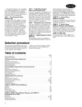
Access Floor Systems can be applied in a building application in a number of ways. The following Carrier products have been grouped in this publication to provide a single source for obtaining information for your application. 45X — Fan Powered Zone Mixing Unit A specific DDC (direct digital controls) controller for this parallel fan powered box will control both the pressure and temperature of the delivered air to the underfloor plenum. A standard airhandling source can provide 55-degree air, the 45X unit will blend the supply and return air to provide a typical 63-degree air underfloor. This...
Open the catalog to page 2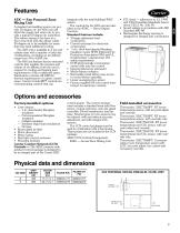
Features 45X — Fan Powered Zone Mixing Unit A standard air-handling source can provide 55-degree air; the 45X unit will blend the supply and return air to provide a typical 63-degree air underfloor. This allows mixing to be done at a floor zone level and also allows colder 55-degree air to be available for areas that may need additional cooling. The 45X unit is available in 2 fan and cabinet sizes with a number of inlet size combinations, providing an air delivery range from 50 to 6200 cfm. The 45X unit features factory-mounted controls that regulate the pressure and volume of air delivery from...
Open the catalog to page 3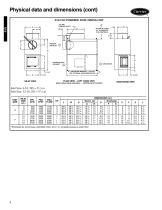
45X FAN POWERED ZONE MIXING UNIT 45X INLET VIEW PLANVIEW - LEFT HAND UNIT DISCHARGE VIEW ‘Estimated for rpm/torque controlled motor, at 0.1 in. wg static pressure under floor.
Open the catalog to page 4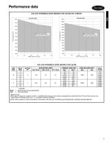
Performance data 45X FAN POWERED ZONE MIXING UNIT (ECM) FAN CURVES Fan Operating Range Outside Operating Range 1800 Fan Operating Range Outside Operating Range 45X FAN POWERED ZONE MIXING UNIT (ECM) UNIT SIZE LEGEND — Electronically Commutated Motor — Full Load Amps *Special order. †This value is based on a signal of 0.03 in. wg differential pressure of the linear averaging flow probe. Minimum Primary flow may be zero. **Rpm/torque controlled motor, at 0.1 in. wg static pressure underfloor. NOTE: Data is based on tests conducted in accordance with ARI (Air Conditioning and Refrigeration Institute)...
Open the catalog to page 5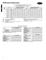
Performance data (cont)45X FAN POWERED ZONE MIXING UNIT — ECM FAN SOUND POWER LEVELS — FAN ONLY UNIT SIZE LEGEND ARI — Air Conditioning and Refrigeration Institute CFM — Air Volume (cubic feet per minute) Lp — Room Sound Pressure NC — ARI 885-98 Test Conditions (see Application Assumptions below) Ps — Static Pressure — — Indicates an NC Level Less Than 20 1. APs is the difference in static pressure from inlet to discharge. 2. Sound power levels are in decibels, re: 10-12 watts. 3. All sound data are based upon tests conducted in accordance with ARI Standard 880-98. 4. NC Application data...
Open the catalog to page 6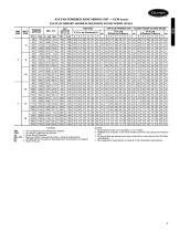
45X FAN POWERED ZONE MIXING UNIT — ECM (cont) FAN PLUS PRIMARY MAXIMUM DISCHARGE SOUND POWER LEVELS INLET SIZE LEGEND Air Conditioning and Refrigeration Institute Air Volume (cubic feet per minute) Room Sound Pressure Minimum Static Pressure Required to Achieve Rated Airflow ARI 885-98 Test Conditions (see Application Assumptions on page 6) Static Pressure NOTES: 1. Sound power levels are in decibels, re: 10-12 watts. 2. Radiated sound power is the noise emitted from the unit casing and induction port. 3. All sound data are based upon tests conducted in accordance with ARI Standard 880-98. 4....
Open the catalog to page 7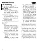
Guide specifications HVAC Guide Specifications Fan Powered Zone Mixing Terminal Unit Size Range: 50 to 6200 Nominal Cfm Carrier Model Number: 45XC — Direct Digital Controls, Carrier CCN Part 1 — General 1.01 SYSTEM DESCRIPTION: Variable speed, parallel fan-powered terminal for access floor application to provide pressure and temperature control to an underfloor air distribution plenum. Manufacturer shall supply unit(s) of the design, number, size and performance as shown on equipment drawings and schedules. A. Insulation shall meet NFPA-90A requirements for flame spread and smoke generation and...
Open the catalog to page 8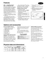
Features 45U — Underfloor Series Flow Fan Powered Unit This unit is designed to be installed in the underfloor plenum and will fit between the pedestals of a standard access floor grid system. The 45U unit can be used to assist with high interior loads (example: conference rooms) or with a ducted primary and available hot water or electric heat for perimeter applications. The 45U unit is available in 2 sizes, providing an air delivery range of 280 to 1200 cfm. The standard PSC (permanent split capacitor) fan motor is available in 120, 208/240 or 277 volts (single-phase, 60 Hz). An optional high-efficiency,...
Open the catalog to page 9All CARRIER commercial catalogs and technical brochures
 A WORLD OF COMFORT PRINT
10 Pages
 A WORLD OF COMFORT (2025)
20 Pages
 19DV
19DV32 Pages
 30XA
30XA136 Pages
 30RAP
30RAP104 Pages
Archived catalogs
 AirStream™ Room Fan Coils
4 Pages
 42B-6SI
24 Pages
 40UV-UH-14SI
32 Pages
 The CRRSA Act (ESSER I)
2 Pages
 AERO® Air-Handling Units
4 Pages
 Axis™ Overhead Air Terminals
4 Pages
 Carrier-Catalogue-2018-2019
940 Pages
 2019 Carrier Ductless
88 Pages
 Carrier VRF
44 Pages
 Axis Overhead Air Terminals
2 Pages
 Roomtop® 50AH036-072
24 Pages
 OMNIZONE™ 50BV020-064
64 Pages
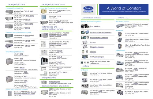 A World of Comfort 2015
2 Pages
 Low Noise Type CABINET FAN
16 Pages
 Performance 16 Heat Pump
4 Pages
 ComfortVIEW 3
6 Pages
 VVT Zoning System
8 Pages
 Heat Reclaim Chillers
2 Pages
 Airstream Unit Ventilators
2 Pages
 Airstream Room Fan Coils
2 Pages
 Aero Air-Handling Units
2 Pages
 17DA Centrifugal Chiller
2 Pages
 AXIS? Overhead Air Terminals
3 Pages
 Comfort? Series
2 Pages
 GEMINI? 38AKS028-044
40 Pages
 i-Vu Open Standard & Plus
2 Pages
 A World of Comfort
2 Pages
 AIRSTREAM™ Room Fan Coils
3 Pages
 ROOMAIR CONDITIONERS
6 Pages
 Water-Cooled Chillers
3 Pages
 Antimicrobial Solutions
3 Pages


- CARRIER heat pump
- CARRIER residential heat pump
- CARRIER air conditioner
- CARRIER air source heat pump
- CARRIER surface-mounted detector
- CARRIER outdoor heat pump
- White thermostat
- Mechanical ventilation unit
- CARRIER white detector
- CARRIER programmable thermostat
- Commercial air conditioning cabinet
- Heating thermostat
- CARRIER digital thermostat
- CARRIER commercial detector
- Split air conditioning unit
- CARRIER wall-mounted thermostat
- Inverter heat pump
- Reversible air conditioner
- Thermostat with digital display
- VirtualExpo Group
- Our Partners
- Careers
- Testimonials