
- Catalogs
- CARRIER commercial
- 42B-6SI


42B-6SI

42B-6SI
Operating air-handling equipment within design specifications is crucial for safety and reliability. Key practices include locking and tagging the fan motor power disconnect switch before servicing, disconnecting all power sources, and ensuring rigging equipment can handle component weight. Avoid pressurizing coils with non-liquids for leak testing and steam-cleaning coils when personnel are nearby to prevent severe injury or death.
This document provides installation instructions for the 42BHE and BVE fan coil units, referencing unit wiring diagrams and emphasizing compliance with the National Electrical Code and local codes.
- Step 1 - Unpack and Inspect Unit: Remove shipping wraps and check for damage.
- Step 2 - Protect Unit from Damage: Ensure protection from adverse weather; not suitable for outdoor installations.
- Step 3 - Prepare Jobsite: Set up a sample installation to check dimensions and instruct trades.
- Step 4 - Prepare Unit: Match power requirements with the available source and remove shipping screws.
- Step 5 - Position Unit: Use provided knockouts for mounting and support until installation is complete.
Procedures include air system balancing, cleaning coils, checking drains, and maintaining fan and motor bearings. Regular maintenance is recommended for optimal performance.
Guidance is provided for issues like excessive condensation and motor overload.
Detailed figures and dimensions emphasize adequate spacing for service access and maneuverability.
- Use vibration isolators for all unit sizes; trapeze suspension is recommended for certain units.
- Ensure the unit is level for proper drainage and operation.
- Maintain minimum clearances for maintenance and safety.
- Protect the unit from debris and ensure no foreign material enters the drain pan.
- Maximum operating altitude is 13,400 ft; all units are IPX0 rated.
Operating weight information and weight correction factors are provided, along with suspension details for specific units.
Ensure proper drainage with a double-sloped condensate drain pan and appropriate piping. Install valves according to manufacturer instructions.
Consult a water treatment expert to ensure compliance with water quality parameters. Proper treatment is essential for warranty and damage prevention.
Perform a hydrostatic test for leaks and insulate piping to prevent sweating. Maximum external static pressures are provided for units at minimum airflow.
Specifications include fan, DX coil connections, and electric heaters, with dimensions and connection details.
Instructions emphasize compliance with NEC requirements and correct motor wiring, highlighting the importance of adhering to codes.
Guidelines stress proper insulation and flexible connections to minimize noise and alignment issues.
Steps for installing a preassembled mixing box include assembling base rails and sealing connections.
Final checks include cleaning the unit, ensuring proper fan operation, and checking for leaks.
Procedures vary based on conditions, advising on avoiding condensation and adjusting chilled water temperature.
Emphasizes completing ductwork and connections before balancing the air system.
Regular tasks include cleaning coils, checking drains, and ensuring proper fan and motor operation.
Units accommodate various filter sizes, with support angle brackets for guidance during insertion.
- Quarterly: Lubricate bearings, adjust belt tension, and change air filter.
- Annually: Inspect wiring, tighten set screws, clean coil and drain pan, and clean blower wheel.
- Excessive Condensation: Solutions include continuous fan operation or switching fan speed.
- Motor Overload: Remedies involve adjusting fan speed or obtaining a motor rated for high temperatures.
A checklist ensures proper start-up of the AIRSTREAM™ system, including visual inspections and verifying system operations.
Catalog excerpts
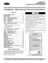
AirStream™ 42BHE,BVE06-40 System Fan Coil Air Conditioners Installation, Start-Up and Service Instructions CONTENTS Page SAFETY CONSIDERATIONS . . . . . . . . . . . . . . . . . . . 1 INTRODUCTION . . . . . . . . . . . . . . . . . . . . . . . . . . . . . . 2 INSTALLATION . . . . . . . . . . . . . . . . . . . . . . . . . . . . . . 2 Step 1 — Unpack and Inspect Unit . . . . . . . . . . . . . . 2 Step 2 — Protect Unit from Damage . . . . . . . . . . . . . 2 Step 3 — Prepare Jobsite . . . . . . . . . . . . . . . . . . . . . . 2 Step 4 — Prepare Unit . . . . . . . . . . . . . . . . . . . . . . . . 9 Step 5 — Position Unit . . . . . . . . . . . . . . . . . . . . . . . . 9 • TOTAL WEIGHT UNIT CORRECTION FACTOR (LB) Step 6 — Make Piping Connections . . . . . . . . . . . . 11 • DRAIN • WATER SUPPLY/RETURN CONNECTIONS • WATER TREATMENT • HYDROSTATIC TEST • INSULATION • MAXIMUM EXTERNAL STATIC PRESSURES Step 7 — Make Electrical Connections . . . . . . . . . . 15 • SERVICE SWITCHES: Step 8 — Make Duct Connections . . . . . . . . . . . . . 16 Step 9 — Install Mixing Box . . . . . . . . . . . . . . . . . . . 16 Step 10 — Make Final Preparations . . . . . . . . . . . . 18 START-UP . . . . . . . . . . . . . . . . . . . . . . . . . . . . . . . . . 19 Air System Balancing . . . . . . . . . . . . . . . . . . . . . . . . 19 SERVICE . . . . . . . . . . . . . . . . . . . . . . . . . . . . . . . . . . 19 Clean Coils . . . . . . . . . . . . . . . . . . . . . . . . . . . . . . . . . 19 Check Drain . . . . . . . . . . . . . . . . . . . . . . . . . . . . . . . . 19 Fan and Motor Bearings . . . . . . . . . . . . . . . . . . . . . . 19 Align Pulley . . . . . . . . . . . . . . . . . . . . . . . . . . . . . . . . 20 Adjust Fan Belt Tension . . . . . . . . . . . . . . . . . . . . . . 20 Clean Fan Wheel . . . . . . . . . . . . . . . . . . . . . . . . . . . . 20 Clean or Replace Air Filters . . . . . . . . . . . . . . . . . . . 20 Recommended Maintenance . . . . . . . . . . . . . . . . . . 20 TROUBLESHOOTING . . . . . . . . . . . . . . . . . . . . . . . . 20 Excessive Condensation on Fan Coil Unit Parts . . 20 Motor Overload . . . . . . . . . . . . . . . . . . . . . . . . . . . . . 20 START-UP CHECKLIST . . . . . . . . . . . . . . . . . . . . . CL-1 SAFETY CONSIDERATIONS Air-handling equipment is designed to provide safe and reliable service when operated within design specifications. To avoid injury to personnel and damage to property or equipment, use good judgment and follow safe practices as outlined below when installing and operating this equipment. See Fig. 1 Proposition 65 warning label. DANGER NEVER REACH INTO a unit while the fan is running. LOCK OPEN AND TAG the fan motor power disconnect switch before working on unit. In addition, remove the fuses and take them with you after noting this on tag. DISCONNECT ALL POWER before attempting any installation or service. More than one power source may be supplied to a unit. Power to remote mounted control devices may not be supplied through the unit. CHECK THE WEIGHT of assembly and components to be sure that rigging equipment can handle them safely. NEVER PRESSURIZE a coil with a non-liquid for leak testing. A dangerous burst may occur. DO NOT STEAM-CLEAN coils until you are sure all personnel are clear of the area. Failure to follow these warnings will result in severe personal injury or death. IMPORTANT: Children should be supervised to ensure that they do not play with the appliance. ! This product can expose you to chemicals including Acrylamide, which is known to the State of California to cause cancer and birth defects or other reproductive harm. For more information, go to www.P65Warnings.ca.gov Ce produit peut vous exposer à des produits chimiques, y compris l’acrylamide, qui est connu dans l’État de Californie pour causer le cancer et des malformations congénitales ou d’autres problèmes de reproduction. Pour de plus amples informations, prière de consulter www.P65Warnings.ca.gov ! Este producto puede exponerlo a productos químicos como la acrilamida, que en el estado de California es causante de cáncer y defects de nacimiento u otros daños reproductivos. Para mayor información, visite www.P65Warnings.ca.gov Fig. 1 — Proposition 65 Warning Label Manufacturer reserves the right to discontinue, or change at any time, specifications or designs without notice and without incurring obligations. Catalog No. 04-53420028-01 Printed in
Open the catalog to page 1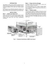
Step 2 — Protect Unit from Damage To maintain warranty, protect unit against adverse weather conditions, theft or vandalism on the jobsite. The described equipment IS NOT suitable for outdoor installations. The equipment should never be stored or installed where it may be subjected to a hostile environment such as rain, snow, or extreme temperatures. The following contains general installation instructions for the 42BHE, BVE fan coil units. See Fig. 2 for components. Refer to the unit wiring diagram installed on the blower housing or specific manufacturer literature for any other type of factory-mounted...
Open the catalog to page 2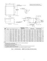
Drawing is provided for reference only. Dimensions may vary with options ordered. NOTES: 1. Unit measurements on drawings and in tables are shown in inches and (millimeters). 2. Right hand shown, left hand opposite. 3. All dimensions are in inches ±1/4 in.(6 mm). 4. Product specifications are subject to change without notice. 5. Right hand shown, left hand opposite. 6. Allow adequate spacing for maneuverability around unit to allow service through recommended access area. 7. “C” dimension is measured from coil side of unit. 8. Mixing Box option will vary return duct dimensions, refer to mixing...
Open the catalog to page 3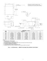
Drawing is provided for reference only. Dimensions may vary with options ordered. NOTES: 1. Right hand shown, Left hand opposite. 2. All dimensions are +/- 1/4” (+/- 6 mm). 3. Drain pan removal is on the piping side of the unit. 4. Allow adequate spacing or maneuverability of unit to allow service through recommended access area. 5. Dimensions in parenthesis are in millimeters. 6. “C” dimension is measured from coil side of unit. 7. Product specifications are subject to change without notice. 8. Mixing Box option will vary return duct dimensions, refer to mixing box details, Fig. 19 page 18....
Open the catalog to page 4All CARRIER commercial catalogs and technical brochures
 A WORLD OF COMFORT PRINT
10 Pages
 A WORLD OF COMFORT (2025)
20 Pages
 19DV
19DV32 Pages
 30XA
30XA136 Pages
 30RAP
30RAP104 Pages
Archived catalogs
 AirStream™ Room Fan Coils
4 Pages
 40UV-UH-14SI
32 Pages
 The CRRSA Act (ESSER I)
2 Pages
 AERO® Air-Handling Units
4 Pages
 Axis™ Overhead Air Terminals
4 Pages
 Carrier-Catalogue-2018-2019
940 Pages
 2019 Carrier Ductless
88 Pages
 Carrier VRF
44 Pages
 Axis Overhead Air Terminals
2 Pages
 Roomtop® 50AH036-072
24 Pages
 OMNIZONE™ 50BV020-064
64 Pages
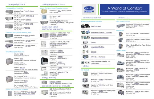 A World of Comfort 2015
2 Pages
 Low Noise Type CABINET FAN
16 Pages
 Performance 16 Heat Pump
4 Pages
 ComfortVIEW 3
6 Pages
 VVT Zoning System
8 Pages
 Heat Reclaim Chillers
2 Pages
 Airstream Unit Ventilators
2 Pages
 Airstream Room Fan Coils
2 Pages
 Aero Air-Handling Units
2 Pages
 17DA Centrifugal Chiller
2 Pages
 AXIS? Overhead Air Terminals
3 Pages
 Comfort? Series
2 Pages
 GEMINI? 38AKS028-044
40 Pages
 i-Vu Open Standard & Plus
2 Pages
 A World of Comfort
2 Pages
 AIRSTREAM™ Room Fan Coils
3 Pages
 ROOMAIR CONDITIONERS
6 Pages
 Water-Cooled Chillers
3 Pages
 Antimicrobial Solutions
3 Pages


- CARRIER heat pump
- CARRIER residential heat pump
- CARRIER air source heat pump
- CARRIER thermostat
- CARRIER surface-mounted detector
- CARRIER outdoor heat pump
- White thermostat
- Mechanical ventilation unit
- CARRIER white detector
- CARRIER programmable thermostat
- Commercial air conditioning cabinet
- Heating thermostat
- CARRIER digital thermostat
- CARRIER commercial detector
- Split air conditioning unit
- CARRIER wall-mounted thermostat
- Inverter heat pump
- Reversible air conditioner
- Thermostat with digital display
- VirtualExpo Group
- Our Partners
- Careers
- Testimonials