
- Catalogs
- CARRIER commercial
- 39LA,LB,LC,LD,LF,LG,LH03-25 Indoor Air Handlers


39LA,LB,LC,LD,LF,LG,LH03-25 Indoor Air Handlers

39LA,LB,LC,LD,LF,LG,LH03-25 Indoor Air Handlers
- Intertwined Circuits: Operations must have intertwined circuits for equal loading, with suction and discharge connections on the same end. Coils must comply with ANSI/ASHRAE 15 standards.
- Hot Water Coils: Feature aluminum plate fins bonded to copper tubes, galvanized steel casings, and copper headers. Working pressure is 175 psig at 400°F.
- Steam Distributing Coils: Non-freeze type with aluminum plate fins, copper tubes, and steel headers. Working pressure is 175 psig at 400°F.
- Electric Heat Coils: Open wire type with 80% nickel and 20% chromium resistance coils, supported in a galvanized steel frame. Includes thermal cutouts for overtemperature protection, meeting UL and NEC requirements.
- Designed to house specific filter types with flat and angle filter sections available. Includes side access slide rails and hinged doors.
- Mixing boxes with parallel blade dampers, rated as low-leakage with a maximum leakage rate of 2% at specified conditions.
- Installed as indicated, featuring double-walled hinged doors.
- Options include variable inlet guide vanes, high-efficiency motors, and various coil types with copper and stainless steel components.
Catalog excerpts

Product Data 39LA,LB,LC,LD,LF,LG,LH03-25 Indoor Air Handlers Nominal 1,800 to 15,000 cfm Carrier 39L Series air handlers offer: • Horizontal and vertical draw-thru arrangements for heating, cooling, ventilation, and VAV applications • Small footprint assures rigging ease and reduced space requirements • High-efficiency fan minimizes surging and turbulence and reduces operating costs • Exclusive Nu-Fin coil surface provides peak heat transfer • Optional double wall construction Features/Benefits Carrier delivers the air handler components for many stringent specification requirements. The 39L series air handlers are compact and fully assembled; they combine versatility with economical, dependable performance. Dependable performance Galvanized steel panels ensure structural integrity under all operating conditions. Double-walled hinged access doors also enhance structural stability and provide fast, easy access. Sloped, double-wall stainless steel drain pan controls condensate and is self-draining; complies with ASHRAE (American Society of Heating, Refrigerating and Air Condi tioning Engineers) Standard 62.1. Copyright 2005 Carrier Corporation 712 Form 39L-6PD
Open the catalog to page 1
Internally mounted motors and drives are installed and aligned at the factory. Because they are contained in a cooled, filtered, dehumidified airstream, motor bearings and belts have less wear and require less servicing. Internal mounting also reduces installation time, shipping damage, and vandalism. Precision-balanced fan wheels limit vibration and eliminate abnormal stress on bearings and other components. Rugged pillow-block bearings are securely fastened to the solid steel fan shafts with split collets and clamp locking devices. Bearings are rated at 200,000 hours average life. Mixing boxes...
Open the catalog to page 2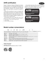
AHRI certification Coils installed in the Carrier 39L air handlers are rated in accordance with AHRI Standard 410 and a detailed description of this industry standard can be found in the Carrier Central Station Air Handler Coils catalog. The Air Conditioning, Heating and Refrigeration Institute (AHRI) is a voluntary, nonprofit organization comprised of the manufacturers of air conditioning, refrigeration, and heating products. More than 90% of the air conditioning and refrigeration machinery and components manufactured in the United States is produced by members of AHRI. Carrier 39L air handlers...
Open the catalog to page 3
LEGEND COMB. — Combination PH — Preheat POS. — Position Factory-installed option components POSITION 4, UNIT CONFIGURATION MODEL (Component Sequence Also Shown) Model number nomenclature (cont) 4
Open the catalog to page 4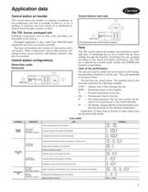
Application data Vertical (indoor unit only) Central station air handler The central station air handler is a heating, ventilating, or air-conditioning unit that is centrally located in, or on, a building or structure and from which air is distributed to desired areas through a system of ducts. The 39L factory packaged unit Individual components, such as fans, coils, and filters, are assembled at the factory. Packaged equipment is less costly than field-fabricated equipment and does not require assembly. The basic air-handling unit consists of a fan section and a coil section. Other components,...
Open the catalog to page 5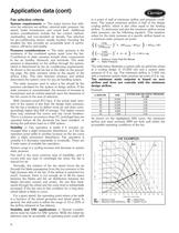
Application data (cont) Fan selection criteria System requirements — The major factors that influence fan selection are airflow, external static pressure, fan speed, brake horsepower, and sound level. Additional system considerations include the fan control method, overloading, and non-standard air density. Fan selection for air-conditioning service usually involves choosing the smallest fan that provides an acceptable level of performance, efficiency and quality. Pressure considerations — The static pressure is the resistance of the combined system apart from the fan. Contributors to static...
Open the catalog to page 6
39L SIZE 12 LA 7 MSE 6 SC 5 TOTAL IN. WG Sound considerations — The fan is one of the main sound sources in an air-conditioning system. Other sources of sound include the duct system and terminals, because they generate turbulence in the air flowing through them. Simply estimating fan sound does not give an accurate picture of total system sound, but because fan sound is a major component of system sound, fan sound should be minimized. To minimize its sound generation, a fan must be correctly sized and should be selected to operate at or near peak efficiency. Oversized fans can generate much...
Open the catalog to page 7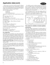
Application data (cont) Power losses in the motor and drive should be allowed for when determining the motor output (bhp), so that the motor can be correctly sized and so that the additional heat output can be subtracted from cooling capacity or added to heating capacity. A typical example follows: Given Fan Operating Point: 13,224 cfm 9.6 Fan bhp 3.0% estimated drive loss Calculate the required fan motor output (Hp) due to drive loss: Hp = (Fan bhp) x (Drive Loss) Hp = 9.6 x 1.03 Hp = 9.89 hp (select 10 Hp motor) Calculate the total fan motor heat output (Q) according to motor efficiency: Q...
Open the catalog to page 8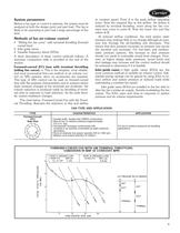
System parameters Before a fan type or control is selected, the system must be analyzed at both the design point and part load. The fan is likely to be operating at part load a large percentage of the time. Methods of fan air-volume control • “Riding the fan curve” with terminal throttling (forward curved fans) • Inlet guide vanes • Variable frequency drives (VFDs) A short description of these control methods follows. A summary comparison table is provided at the end of the section. Forward-curved (FC) fans with terminal throttling (riding fan curve) — This is the simplest, most reliable, and...
Open the catalog to page 9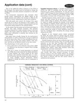
Application data (cont) Due to the additional airflow resistance of the IGVs in the airstream, fan speed must be increased to obtain the design airflow and static pressure compared to a unit without IGVs. The horsepower requirement also increases. Even though power requirements are slightly higher at the design pressure and airflow, the increase is offset by the reduction in power requirements at part load conditions. With inlet guide vane control, the closing of the vanes causes the air to spin in the direction of fan rotation. The spin results in less static pressure being generated and less...
Open the catalog to page 10All CARRIER commercial catalogs and technical brochures
 A WORLD OF COMFORT PRINT
10 Pages
 A WORLD OF COMFORT (2025)
20 Pages
 19DV
19DV32 Pages
 30XA
30XA136 Pages
 30RAP
30RAP104 Pages
Archived catalogs
 AirStream™ Room Fan Coils
4 Pages
 42B-6SI
24 Pages
 40UV-UH-14SI
32 Pages
 The CRRSA Act (ESSER I)
2 Pages
 AERO® Air-Handling Units
4 Pages
 Axis™ Overhead Air Terminals
4 Pages
 Carrier-Catalogue-2018-2019
940 Pages
 2019 Carrier Ductless
88 Pages
 Carrier VRF
44 Pages
 Axis Overhead Air Terminals
2 Pages
 Roomtop® 50AH036-072
24 Pages
 OMNIZONE™ 50BV020-064
64 Pages
 A World of Comfort 2015
2 Pages
 Low Noise Type CABINET FAN
16 Pages
 Performance 16 Heat Pump
4 Pages
 ComfortVIEW 3
6 Pages
 VVT Zoning System
8 Pages
 Heat Reclaim Chillers
2 Pages
 Airstream Unit Ventilators
2 Pages
 Airstream Room Fan Coils
2 Pages
 Aero Air-Handling Units
2 Pages
 17DA Centrifugal Chiller
2 Pages
 AXIS? Overhead Air Terminals
3 Pages
 Comfort? Series
2 Pages
 GEMINI? 38AKS028-044
40 Pages
 i-Vu Open Standard & Plus
2 Pages
 A World of Comfort
2 Pages
 AIRSTREAM™ Room Fan Coils
3 Pages
 ROOMAIR CONDITIONERS
6 Pages
 Water-Cooled Chillers
3 Pages
 Antimicrobial Solutions
3 Pages


- CARRIER heat pump
- CARRIER residential heat pump
- CARRIER air conditioner
- CARRIER air source heat pump
- CARRIER thermostat
- CARRIER surface-mounted detector
- CARRIER outdoor heat pump
- White thermostat
- Mechanical ventilation unit
- CARRIER white detector
- CARRIER programmable thermostat
- Commercial air conditioning cabinet
- Heating thermostat
- CARRIER digital thermostat
- CARRIER commercial detector
- Split air conditioning unit
- CARRIER wall-mounted thermostat
- Inverter heat pump
- Reversible air conditioner
- Thermostat with digital display