
- Catalogs
- CAME S.P.A
- SWING-GATE OPERATOR

SWING-GATE OPERATOR
SWING-GATE OPERATOR
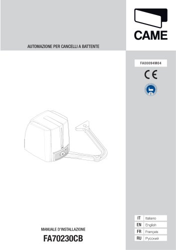
This document serves as an installation manual for the FA70230CB automation system for swing gates, designed for residential or condominium use. It highlights the importance of using the product solely for its intended purpose and warns against improper use.
Key safety instructions include avoiding crushing hazards, ensuring no transit during operation, and maintaining a safe distance from moving parts. The manual emphasizes reading and retaining safety warnings and installation manuals.
Before installation, verify the mechanical condition of the gate, ensure it is balanced, and check for proper opening and closing. Additional protections or warnings may be necessary if the automation is installed below 2.5 meters. Ensure no entrapment risks with surrounding structures.
Installation should be performed by qualified personnel. The site should be adequately marked to prevent unauthorized access, especially by children. All control devices must be installed at a safe distance from the gate's movement area.
The FA70230CB model has an IP54 protection rating, operates on 230V AC, and has a power consumption of 160W. It is designed for gates up to 2.3 meters per leaf and includes a motor with a maximum torque of 180 Nm.
The manual provides detailed instructions for installing the automation system, including the placement of corrugated tubes for wiring, fixing brackets, and ensuring the motor is securely attached. It includes diagrams for reference.
Regular maintenance checks are advised to ensure the system's functionality and safety. Users should keep the gate's movement area clear and ensure children do not play with control devices. Any repairs or adjustments should be performed by qualified technicians.
The document concludes with a reminder to record maintenance activities and adhere to all safety and installation guidelines to ensure the reliable operation of the automation system.
The document outlines the transmission to the shaft using a washer for the slow shaft and a screw. It specifies the use of UNI 5739 M6x10, UNI 6593 Ø 6, and UNI 6592 Ø 12 components. The manual is subject to change without notice.
If the system has stop points for both opening and closing, end-of-travel adjustments are unnecessary. Otherwise, adjustments should be made by unlocking the gear motor and fixing the driven arm to the gate bracket. The document details the adjustment of micro switches and cams for both opening and closing positions.
Before working on the control panel, disconnect the power and batteries. The connections are protected by fast fuses, with specific fuses for line, accessories, and board. The document describes the terminal blocks for various components, including motor reducers, power supply, and safety devices. It also covers the power supply specifications and the connection of signaling devices.
Instructions are provided for installing automation on the left or right, with specific electrical connections for each configuration. The document includes details on connecting the automation and gear motor, with default settings for delayed closure.
Instructions for inserting the AF card to control automation with a transmitter are provided. The document describes the stop button function and the use of safety devices like photocells, which comply with EN 12978 standards.
The document explains the adjustment of trimmers for automatic closure time, work time, and delay time for M2 in closure. It also describes DIP switch functions for automatic closure and sequential operation.
After completing connections and setup, the cover should be placed on the gear motor, and the motor should be locked with a key. Manual unlocking of the gear motor should be done without power to avoid uncontrolled gate movement.
Specific operations differ from standard installation, including bracket fixing and determining fixing points according to provided dimensions.
Regular maintenance should be performed with the power off to avoid accidental movements. A maintenance log is provided for user records. Troubleshooting guidance is included for common issues like gate not opening or closing, with solutions such as checking power supply and cleaning photocells.
Extraordinary maintenance should be performed by specialized technicians, with a log provided for recording interventions by external companies.
CAME S.p.A. adheres to an Environmental Management System certified under UNI EN ISO 14001. Users are encouraged to follow proper disposal practices for packaging and product components, ensuring compliance with local regulations.
The document outlines the proper disposal methods for packaging and product materials. Packaging materials like cardboard and plastic should be disposed of as solid urban waste and separated for recycling. It is crucial to comply with local laws before dismantling and disposing of the product. Hazardous components such as control boards and batteries must be disposed of by certified professionals.
The product complies with current regulations, and the document provides contact information for Came S.p.A. in Italy.
Catalog excerpts
CAME AUTOMAZIONE PER CANCELLI A BATTENTE
Open the catalog to page 1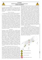
PRODOTTO DEVE ESSERE DESTINATO SOLO ALL’USO PER IL QUALE È STATO ESPRESSAMENTE STUDIATO. OGNI ALTRO USO È DA CONSIDERARSI PERICOLOSO. CAME S.P.A NON È RESPONSABILE PER EVENTUALI DANNI CAUSATI DA USI IMPROPRI, ERRONEI ED IRRAGIONEVOLI • CONSERVARE QUESTE AVVERTENZE ASSIEME AI MANUALI DI INSTALLAZIONE E D’USO DEI COMPONENTI L’IMPIANTO DI AUTOMAZIONE. PRIMA DELL’INSTALLAZIONE (VERIFICA DELL’ESISTENTE: NEL CASO DI VALUTAZIONE NEGATIVA, NON PROCEDERE PRIMA DI AVER OTTEMPERATO AGLI OBBLIGHI DI MESSA IN SICUREZZA) • CONTROLLARE CHE LA PARTE DA AUTOMATIZZARE SIA IN BUONO STATO MECCANICO, CHE SIA BILANCIATA...
Open the catalog to page 2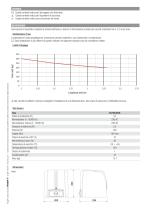
LEGENDA Questo simbolo indica parti da leggere con attenzione. Questo simbolo indica parti riguardanti la sicurezza. ☞ Questo simbolo indica cosa comunicare all’utente. DESCRIZIONE Automazione irreversibile completa di scheda elettronica e braccio di trasmissione snodato per cancelli a battente fino a 2,3 m per anta. Destinazione d'uso L’automazione è stata progettata per motorizzare cancelli a battente a uso residenziale o condominiale. Ogni installazione e uso difformi da quanto indicato nel seguente manuale sono da considerarsi vietate. Limiti d’impiego 350 300 Lunghezza anta (m) Nei cancelli...
Open the catalog to page 3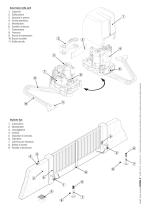
Descrizione delle parti 1. Coperchio Pag. 4 - Codice manuale: FA00094-IT- ver. 3 - 01/2017 - © Came S.p.A. -1contenuti delmanuale sono da ritenersisuscettibili dimodifica in qualsiasi momento senza obbligo dipreavviso
Open the catalog to page 4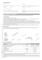
Applicazione con braccio di trasmissione dritto e guida di scorrimento (STYLO-BD). Pag. 5 - Codice manuale: FA00094-IT- ver. 3 - 01/2017 - © Came S.p.A. -1contenuti delmanuale sono da ritenersisuscettibili dimodifica in qualsiasi momento senza obbligo dipreavviso INDICAZIONI GENERALI PER L'INSTALLAZIONE A L'installazione deve essere effettuata da personale qualificato ed esperto e nel pieno rispetto delle normative vigenti. A Prima di procedere all'installazione e necessario: • verificare che la struttura del cancello sia adeguatamente robusta, le cerniere siano efficienti e che non vi siano...
Open the catalog to page 5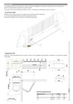
INSTALLAZIONE Le seguenti illustrazioni sono solo esempi, in quanto lo spazio per il fissaggio del motoriduttore e degli accessori varia a seconda degli ingombri. Spetta all’installatore scegliere la soluzione più adatta. I disegni si riferiscono all’automazione installata a sinistra. L’installazione del motoriduttore a destra è simmetrica. Posa dei tubi corrugati Fissaggio delle staffe Determinare il punto di fissaggio della staffa cancello e ricavare il punto di fissaggio della staffa pilastro, rispettando le quote riportate nel disegno e nella tabella. Pag. 6 - Codice manuale: FA00094-IT...
Open the catalog to page 6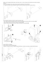
Segnare i punti di fissaggio della staffa pilastro e della staffa cancello. Le misure di interasse dei fori delle staffe sono indicate nel paragrafo dimensioni. Forare i punti di fissaggio, inserire i tasselli o utilizzare degli inserti adeguati per la tenuta delle staffe. I disegni sono indicativi, spetta all’installatore scegliere la soluzione più adatta a seconda del tipo e spessore dell’anta. Pag. 7 - Codice manuale: FA00094-IT - ver. 3 - 01/2017 - © Came S.p.A. - I contenuti del manuale sono da ritenersi suscettibili di modifica in qualsiasi momento senza obbligo di preavviso Prima di...
Open the catalog to page 7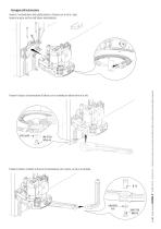
Fissaggio dell’automazione Fissare il braccio di trasmissione all’albero con la rondella per albero lento e la vite. Fissare il braccio condotto al braccio di trasmissione con il perno, la vite e la rondella. Pag. 8 - Codice manuale: FA00094-IT - ver. 3 - 01/2017 - © Came S.p.A. - I contenuti del manuale sono da ritenersi suscettibili di modifica in qualsiasi momento senza obbligo di preavviso Inserire il motoriduttore nella staffa pilastro e fissarlo con le viti e i dadi. Inserire la spina nel foro dell’albero motorid
Open the catalog to page 8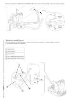
Pag. 9 - Codice manuale: FA00094-IT- ver. 3 - 01/2017 - © Came S.p.A. -1contenuti delmanuale sono da ritenersisuscettibili dimodifica in qualsiasi momento senza obbligo dipreavviso Determinazione dei punti di finecorsa C3 Se nell'impianto sono presenti delle battute di arresto sia in apertura che in chiusura, non e necessario regolare i finecorsa. In caso contrario, procedere con la regolazione.
Open the catalog to page 9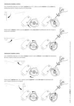
Automazione installata a sinistra. Con il motoriduttore sbloccato e con l’anta in apertura (max 110°), ruotare la camma inferiore in senso orario fino all’attivazione del micro. Fissare la camma con la vite centrale. Automazione installata a destra. Con il motoriduttore sbloccato e con l’anta in chiusura, ruotare la camma inferiore in senso orario fino all’attivazione del micro. Fissare la camma con la vite centrale. Portare l’anta in apertura (max 110°), ruotare la camma superiore in senso anti-orario fino all’attivazione del micro. Fissare la camma con le viti laterali. Pag. 10 - Codice manuale:...
Open the catalog to page 10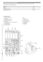
A Attenzione! Prima di intervenire sul quadro comando, togliere la tensione di linea e, se presenti, scollegare le batterie. Tutte le connessioni sono protette da fusibili rapidi. 6. Morsettiera per dispositivi di comando e sicurezza
Open the catalog to page 11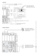
Alimentazione 230 V AC 50/60 Hz Per variare la coppia motore, spostare il faston indicato su una delle 4 posizioni; da 1 (min) a 4 (max). Bianco Rosso Nero Uscita alimentazione accessori 24 V AC. Potenza: max 20 W. Dispositivi di segnalazione Uscita collegamento lampeggiante (Portata contatto: 230 V AC - 25 W max). Lampeggia durante le fasi di apertura e chiusura del cancello. Uscita segnalazione cancello aperto (Portata contatto: 24 V AC - 3 W max). Segnala la posizione del cancello aperto, si spegne quando il cancello è chiuso. Pag. 12 - Codice manuale: FA00094-IT - ver. 3 - 01/2017 - © Came...
Open the catalog to page 12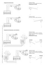
Collegamenti elettrici: automazione installata a sinistra (vista interna). (Predisposizione di default) Collegamento dell’automazione Bianco Rosso Collegamenti elettrici: automazione installata a destra (vista interna). Pag. 13 - Codice manuale: FA00094-IT - ver. 3 - 01/2017 - © Came S.p.A. - I contenuti del manuale sono da ritenersi suscettibili di modifica in qualsiasi momento senza obbligo di preavviso Bianco Rosso Collegamento dell’automazione e del motoriduttore Collegamenti elettrici: automazione installata a sinistra e motoriduttore installato a destra (vista interna) con automazione ritardata...
Open the catalog to page 13All CAME S.P.A catalogs and technical brochures
 Operator for swing gates
128 Pages
 FA00096M4A
2 Pages
 RSE
RSE24 Pages
- Security bollard
- Public space bollard
- Industrial barrier
- Metal bollard
- Door intercom
- Industrial thermostat
- Metal barrier
- Public space barrier
- Outdoor bollard
- White thermostat
- Programmable thermostat
- Heating thermostat
- Digital thermostat
- Wall-mounted thermostat
- Industrial turnstile
- Commercial turnstile
- Thermostat with digital display
- Gate automation
- Stainless steel bollard
- Room thermostat