

RSE
RSE
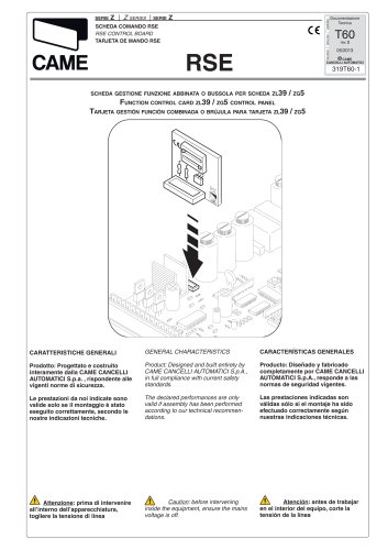
The RSE control board, manufactured by CAME CANCELLI AUTOMATICI S.p.A., complies with current safety standards. Proper assembly according to technical guidelines is essential for optimal performance. Always disconnect the mains voltage before servicing.
1. RSE Serial Board Coupling: Optional for connecting interlock or combined barriers.
2. Function Dip-Switches: Enable interlock or combined functions by inserting the RSE serial board onto the ZG5 MASTER board.
This function allows simultaneous control of two barriers. Install the RSE board on both barriers, connect the terminal boards, and set the dip switches: Dip switch no. 2 on the MASTER barrier to ON and dip switches nos. 6 and 7 on the SLAVE barrier’s ZG5 board to ON.
All command, safety, and accessory devices must connect to the MASTER barrier, except for the fluorescent tube on each barrier. The command devices on the MASTER barrier’s electronic board control stopping, opening, and closing both barriers.
Install the AF board only on the MASTER barrier and save the radio transmitter code on the motherboard. CH1 radio channel commands both MASTER and SLAVE barriers, while CH2 commands only the MASTER barrier.
Enable or disable functions using dip switches, such as automatic closing, obstacle detection, and safety test functions, primarily configured on the MASTER barrier.
Install the RSE board on both barriers and configure the dip switches to enable the interlock function, ensuring one barrier remains locked while the other is in motion.
The document details the setup and configuration of MASTER and SLAVE barriers using RSE and ZG5 boards. It specifies dip switches for functions like automatic opening and interlock, ensuring one barrier remains locked while the other moves.
1. Connect the RSE board to both barriers and set specific dip switches for combined operation.
2. For automatic opening of the second barrier after the first completes its cycle, set dip switch no. 2 on the MASTER barrier to ON.
3. Install the AF board only on the MASTER barrier and save the radio transmitter code.
Emphasizes connecting all command devices to the MASTER barrier and ensuring safety devices are properly connected to prevent unauthorized movements. Highlights the need for pre-flashing and obstacle detection functions for safety.
- Automatic closing: Enabled by setting dip switch 1 to ON on both barriers.
- Open-close-reverse function: Controlled by dip switch 2, with different settings for MASTER and SLAVE barriers.
- Safety test function: Ensures the efficiency of photoelectric cells.
In emergencies, manually releasing the gearmotor with a key allows one barrier to open, releasing the other.
Details on connecting command devices to the MASTER barrier's electronic board, including specific terminal connections for safety and signaling devices.
Instructions for installing and configuring radio control channels for both MASTER and SLAVE barriers, with specific dip switch settings for different command functions.
To open both barriers, activate the control device connected to terminals 2-3. For emergencies, manual disengagement of the motor reducer allows one barrier to open while the other is disabled.
The control devices connected to the MASTER barrier's electronic board have specific functions, such as stopping both barriers or opening only the MASTER or SLAVE barrier. Automatic closure can be activated by setting dip switch 1 to ON for both barriers.
Catalog excerpts
Documentazione Tecnica SCHEDA COMANDO RSE RSE CONTROL BOARD TARJETA DE MANDO RSE CAME CANCELLI AUTOMATICI SCHEDA GESTIONE FUNZIONE ABBINATA O BUSSOLA PER SCHEDA ZL39 FUNCTION CONTROL CARD ZL39 / ZG5 CONTROL PANEL TARJETA GESTIÓN FUNCIÓN COMBINADA O BRÚJULA PARA TARJETA ZL39 / ZG5 GENERAL CHARACTERISTICS CARACTERÍSTICAS GENERALES Prodotto: Progettato e costruito interamente dalla CAME CANCELLI AUTOMATICI S.p.a. , rispondente alle vigenti norme di sicurezza. Product: Designed and built entirely by CAME CANCELLI AUTOMATICI S.p.A., in full compliance with current safety standards. Producto: Diseñado y fabricado completamente por CAME CANCELLI AUTOMATICI S.p.A., responde a las normas de seguridad vigentes. Le prestazioni da noi indicate sono valide solo se il montaggio è stato eseguito correttamente, secondo le nostre indicazioni tecniche. The declared performances are only valid if assembly has been performed according to our technical recommendations. Las prestaciones indicadas son válidas sólo si el montaje ha sido efectuado correctamente según nuestras indicaciones técnicas. Attenzione: prima di intervenire all’interno dell’apparecchiatura, togliere la tensione di linea Caution: before intervening inside the equipment, ensure the mains voltage is off. Atención: antes de trabajar en el interior del equipo, corte la tensi
Open the catalog to page 1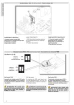
ITALIANO - ENGLISH - ESPAÑOL SCHEDA SERIALE RSE / RSE SERIAL BOARD / TARJETA SERIAL RSE COMPONENTI PRINCIPALI MAIN COMPONENTS COMPONENTES PRINCIPALES 1-Innesto scheda seriale RSE (opzionale per collegamento barriere in abbinato o bussola) 2-Dip-switch funzioni. 1-RSE serial board coupling (optional for connecting interlock or combined barriers) 2-Function dip-switches. 1- Conector tarjeta serial RSE (opcional para la conexión de barreras en combinadas o interbloqueadas) 2-Dip-switches funciones. SELEZIONI FUNZIONI RSE / RSE FUNCTION SELECTIONS / SELECCIONES DE LAS FUNCIONES RSE BUSSOLA INTERLOCK...
Open the catalog to page 2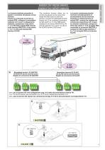
La funzione abbinato permette di gestire il comando simultaneo di due barriere. Inserire su entrambe le barriere la scheda RSE, collegare le morsettiere dedicate (ref. 2) per il collegamento abbinato, posizionare il dip switch n° 2 in ON della scheda RSE inserita sulla barriera MASTER e il dip switch n° 6 e 7 in ON sulla scheda ZG5 barriera SLAVE. La función combinada permite controlar simultáneamente el accionamiento de dos barreras. Conecte en ambas barreras la tarjeta RSE, conecte las regletas de conexiones específicas (ref. 2) para la conexión combinada, coloque en ON el dip switch n° 2 de...
Open the catalog to page 3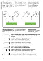
ITALIANO - ENGLISH - ESPAÑOL Tutti i dispositivi di comando, di sicurezza e gli accessori (es. le cupole lampeggianti delle due barriere collegate ai morsetti 10-E7) devono essere collegati alla barriera MASTER, tranne per il cordone luminoso collegato sui morsetti 10-E6 di ogni singola barriera. All the command, safety and accessory devices (e.g. the flashing domes of the two barriers connected to terminals 10E7) must be connected to the MASTER barrier except for the flourescent tube connected on terminals 10-E6 of each barrier. Todos los dispositivos de mandos, de seguridad y los accesorios...
Open the catalog to page 4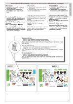
PROCEDURE A - Install the AF board only on the MASTER barrier. B - Save the code of the radio transmitter on the motherboard. PROCEDIMIENTO A - Conecte la tarjeta AF sólo en la barrera MASTER. B - Memorice la codificación del transmisor radio en la placa base. 1)Il canale radio CH1 gestisce il comando delle barriere MASTER e SLAVE e il trasmettitore esegue la seguente funzione: Dip n° 2 OFF- Comando “apre-chiudeinversione” Dip n° 2 ON- Comando “apertura” 1)The CH1 radio channel commands the MASTER and SLAVE barriers and the transmitter performs the following function: Dip switch no. 2 OFF- “Open-closereverse”...
Open the catalog to page 5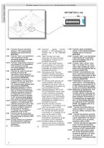
ITALIANO - ENGLISH - ESPANOL 1 ON Funzione chiusura automatica attivata; (1 OFF-disattivata)(da abilitare solo sulla barriera MASTER); 2 ON Funzione "apre" con trasmettitore radio (scheda AF inserita) attivato(da abilitare solo sulla barriera MASTER); con pulsante (2-7) e trasmettitore radio (scheda AF inserita) attivato(da abilitare solo sulla barriera MASTER); 3 ON Funzione ad "azione mantenuta" (esclude la funzione del trasmettitore radio) attivato; (3 OFF disattivato)(da abilitare solo sulla barriera MASTER); chiusura attivato, con dispositivo collegato sui morsetti 10- E7 (4 OFF disattivato)(da...
Open the catalog to page 6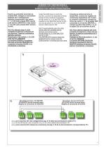
Inserire su entrambe le barriere la scheda RSE, collegare le morsettiere dedicate per il collegamento abbinato, posizionare il dip switch n° 1 in ON della scheda RSE inserita sulla barriera MASTER e il dip switch n° 6 in ON sulla scheda ZG5 barriera SLAVE. N.B. Per ottenere dopo il ciclo completo di apertura e chiusura di una barriera, l’apertura automatica dell’altra barriera. Posizionare il dip switch n° 2 in ON della barriera MASTER. La funzione BUSSOLA mantiene bloccata la barriera MASTER fino a quando la barriera SLAVE è in movimento e viceversa. Conecte en ambas barreras la tarjeta RSE,...
Open the catalog to page 7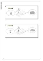
ITALIANO - ENGLISH - ESPAÑOL
Open the catalog to page 8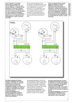
Tutti i dispositivi di comando devono essere collegati alia barriera MASTER, mentre per ogni barriera effettuare i collegamenti del dispositivo di sicurezza collegato ai morsetti 2-C1 (es. fotocellula con funzione di riapertura), del dispositivo (es. spira magnetica) collegato ai morsetti 2-C5 (chiusura immediata) e degli accessori di segnalazione (es. lampeggiatore a cupola e cordone luminoso). All the command devices must be connected to the MASTER barrier, while for all barriers perform the connections of the safety device connected to terminals 2-C1 (e.g. photoelectric cell with re-opening...
Open the catalog to page 9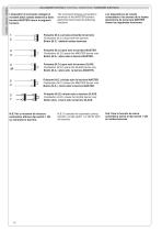
ITALIANO - ENGLISH - ESPAÑOL COLLEGAMENTI ELETTRICI I dispositivi di comando collegati ai morsetti della scheda elettronica della barriera MASTER hanno le seguenti funzioni: / ELECTRICAL CONNECTIONS / CONEXIONES ELÊCTRICAS The command devices connected to terminals of the MASTER barrier’s electronic board have the following functions: Pulsante (N.C.) arresta entrambe le barriere Pushbutton (N.C.) stops both the barriers Botón (N.C. ) detiene ambas barreras Pulsante (N.O.) apre solo la barriera MASTER Pushbutton (N.O.) opens the MASTER barrier only Botón (N.A. ) abre sólo la barrera MASTER. Pulsante...
Open the catalog to page 10All CAME S.P.A catalogs and technical brochures
 Operator for swing gates
128 Pages
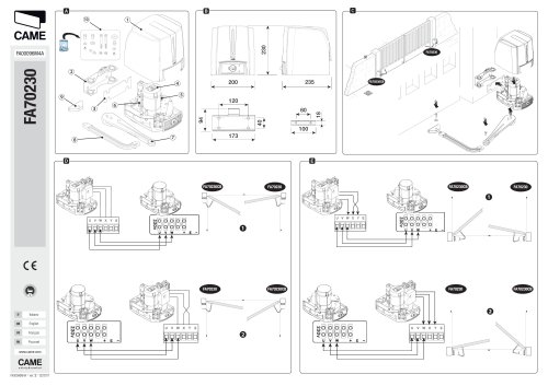 FA00096M4A
2 Pages
 SWING-GATE OPERATOR
96 Pages
- Security bollard
- Public space bollard
- Metal bollard
- Door intercom
- Industrial thermostat
- Metal barrier
- Public space barrier
- Outdoor bollard
- White thermostat
- Programmable thermostat
- Heating thermostat
- Digital thermostat
- Wall-mounted thermostat
- Industrial turnstile
- Commercial turnstile
- Thermostat with digital display
- Gate automation
- Stainless steel bollard
- Room thermostat