
- Catalogs
- CAME S.P.A
- Operator for swing gates

Operator for swing gates
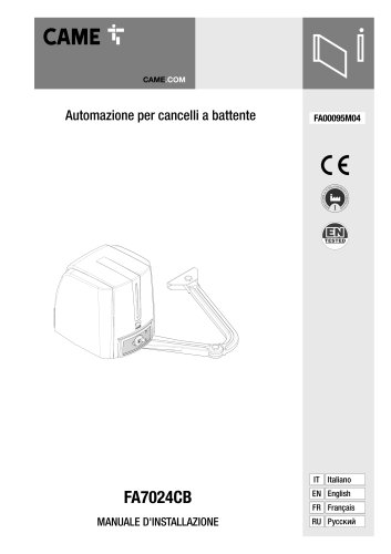
Operator for swing gates
This document serves as an installation manual for the FA7024CB swing gate automation system by Came S.p.A., covering safety instructions, installation procedures, technical specifications, and user recommendations.
Ensure the gate is mechanically sound, balanced, and operates correctly before installation. Additional safety measures are required for installations below 2.5 meters. Avoid improper use to prevent hazards, and retain the manual for future reference.
Verify the gate's mechanical condition, balance, and alignment. Ensure mechanical stops are present and check for potential entrapment risks. Avoid installation on uneven surfaces or areas affected by irrigation.
Installations should be performed by qualified personnel. Secure the site to prevent unauthorized access and install controls at least 1.85 meters from the gate's maneuver area. Compliance with EN 12453 standards is required.
The FA7024CB features a protection grade of IP54, operates on 230V AC with a motor supply of 24V DC, and has a power consumption of 140W. It is designed for intensive use within a temperature range of -20°C to +55°C.
Prepare corrugated tubes for wiring and determine fixing points for gate and pillar brackets. Install the motor reducer in a protected area using appropriate tools and materials for safe installation.
Keep the maneuver area clear and regularly check for wear or damage. Perform functional checks on photocells and sensitive edges every six months. Ensure children do not play with control devices.
The document details the assembly and installation procedures for a motorized gate system, including key components like the transmission arm and mechanical stops. Specific screws and washers are recommended for secure assembly.
Disconnect the power supply and batteries before working on the control panel. The system includes terminals for connecting signaling devices, motor reducers, command devices, and safety devices, with detailed configuration instructions.
The system supports safety devices like photocells and sensitive edges, compliant with EN 12978 standards, which can trigger actions such as reopening during closure or stopping the gate in case of obstacles.
A comprehensive list of functions (F1 to F68) is provided for programming, including total stop, safety test, automatic closure time, and speed adjustments. User management functions and motor settings are also detailed.
The system supports wireless devices and remote protocols like Came Remote Protocol (CRP) for integration with home automation systems. Specific functions are associated with wireless inputs, and errors are displayed if configurations are incorrect.
The document explains menu navigation using the ENTER, ESC, and arrow keys for setting and confirming values, emphasizing that the system cannot be used while the menu is active.
Installation and operational guidelines emphasize placing control commands at least 1.5 meters above the ground to prevent unauthorized access. Compliance with EN 12453 standard regarding impact forces is required, and all safety devices must be functional before delivery.
Keep gate operation areas clean and free of obstructions. Photocells should be clear of vegetation, and remote control devices should be kept away from children. Regular checks for malfunctions and lubrication of moving parts are recommended.
The FA7024CB has a protection rating of IP54, operates on a 230 AC power supply, and has a motor power supply of 24 DC. It has a standby consumption of 5.5 W, a power output of 140 W, and a torque of 180 Nm. The opening time ranges from 13 to 30 seconds.
Qualified personnel should perform installations. Preliminary checks include ensuring the gate structure is sturdy and hinges are efficient. Mechanical stops should be used if ground stops are unavailable.
All electrical connections are protected by quick-fuses. Disconnect the control panel from the main power supply before any work. Detailed instructions are provided for connecting components.
Avoid entering the operator's area during movement and do not counter the operator's movement. Dangerous points should be labeled with specific pictograms. Maintenance or cleaning should only be performed with the power supply cut off.
Disconnect the mains power supply and any batteries before installing plug-in cards. The system supports connections for flashing or cycle lights and gate-open signal outputs with specific voltage and power ratings.
Details are provided for connecting operators and gearmotors, including wiring instructions for both right and left installations, emphasizing correct electrical connections.
Safety devices must comply with EN 12978 provisions. Functions include reopening during closing, reclosing during opening, partial stops, and obstacle waits. Deactivate unused contacts during programming.
The system supports wireless devices via the RIO-CONN card and serial connections through the RS485 with the RSE card. Proper configuration is necessary to avoid error messages related to radiofrequency interferences.
Instructions are provided for entering and navigating the programming menu using the ENTER, ESC, and arrow keys. Programming should start with specific functions like MOTOR TYPE and TRAVEL CALIBRATION.
A comprehensive list of functions is provided, detailing their default settings and possible configurations, including total stop, safety tests, command modes, and various timing adjustments.
Programming should be done when the operator is stopped, and up to 25 users can be memorized. Proper configuration is essential for correct and safe system operation.
Catalog excerpts
Automazione per cancelli a battente FA00095M04
Open the catalog to page 1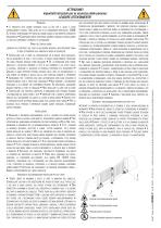
ATTENZIONE! importanti istruzioni per la sicurezza delle persone: LEGGERE ATTENTAMENTE! PRODOTTO DEVE ESSERE DESTINATO SOLO ALL’USO PER IL QUALE È STATO ESPRESSAMENTE STUDIATO. OGNI ALTRO USO È DA CONSIDERARSI PERICOLOSO. CAME S.P.A NON È RESPONSABILE PER EVENTUALI DANNI CAUSATI DA USI IMPROPRI, ERRONEI ED IRRAGIONEVOLI • CONSERVARE QUESTE AVVERTENZE ASSIEME AI MANUALI DI INSTALLAZIONE E D’USO DEI COMPONENTI L’IMPIANTO DI AUTOMAZIONE. PRIMA DELL’INSTALLAZIONE (VERIFICA DELL’ESISTENTE: NEL CASO DI VALUTAZIONE NEGATIVA, NON PROCEDERE PRIMA DI AVER OTTEMPERATO AGLI OBBLIGHI DI MESSA IN SICUREZZA)...
Open the catalog to page 2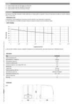
LEGENDA Questo simbolo indica parti da leggere con attenzione. Questo simbolo indica parti riguardanti la sicurezza. ☞ Questo simbolo indica cosa comunicare all’utente. DESCRIZIONE Automazione irreversibile completa di scheda elettronica con display garfico a segmenti e braccio di trasmissione snodato per cancelli a battente fino a 2,3 m per anta. Destinazione d'uso L’automazione è stata progettata per motorizzare cancelli a battente a uso residenziale o condominiale. Ogni installazione e uso difformi da quanto indicato nel seguente manuale sono da considerarsi vietate. Limiti d’impiego 350...
Open the catalog to page 3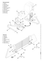
Descrizione delle parti 1. Coperchio Pag. 4 - Codice manuale: FA00095-IT - ver. 4 - 08/2017 - © Came S.p.A. -1 contenuti del manuale sono da ritenersi suscettibili di modifica in qualsiasi momento senza obbligo dipreavviso
Open the catalog to page 4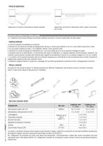
Applicazione con braccio di trasmissione dritto e guida di scorrimento (STYLO-BD). INDICAZIONI GENERALI PER L'INSTALLAZIONE Pag. 5 - Codice manuale: FA00095-IT - ver. 4 - 08/2017 - © Came S.p.A. -1 contenuti del manuale sono da ritenersi suscettibili di modifica in qualsiasi momento senza obbligo di preavviso A L’installazione deve essere effettuata da personale qualificato ed esperto e nel pieno rispetto delle normative vigenti. A Prima di procedere all’installazione e necessario: • verificare che la struttura del cancello sia adeguatamente robusta, le cerniere siano efficienti e che non vi...
Open the catalog to page 5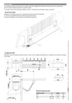
INSTALLAZIONE Le seguenti illustrazioni sono solo esempi, in quanto lo spazio per il fissaggio del motoriduttore e degli accessori varia a seconda degli ingombri. Spetta all’installatore scegliere la soluzione più adatta. I disegni si riferiscono all’automazione installata a sinistra. L’installazione del motoriduttore a destra è simmetrica. Posa dei tubi corrugati Fissaggio delle staffe Determinare il punto di fissaggio della staffa cancello e ricavare il punto di fissaggio della staffa pilastro, rispettando le quote riportate nel disegno e nella tabella. Pag. 6 - Codice manuale: FA00095-IT...
Open the catalog to page 6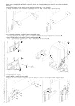
Segnare i punti di fissaggio della staffa pilastro e della staffa cancello. Le misure di interasse dei fori delle staffe sono indicate nel paragrafo dimensioni. Forare i punti di fissaggio, inserire i tasselli o utilizzare degli inserti adeguati per la tenuta delle staffe. I disegni sono indicativi, spetta all’installatore scegliere la soluzione più adatta a seconda del tipo e spessore dell’anta. Pag. 7 - Codice manuale: FA00095-IT - ver. 4 - 08/2017 - © Came S.p.A. - I contenuti del manuale sono da ritenersi suscettibili di modifica in qualsiasi momento senza obbligo di preavviso Prima di...
Open the catalog to page 7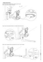
Fissaggio dell’automazione Fissare il braccio di trasmissione all’albero con la rondella per albero lento e la vite. Fissare il braccio condotto al braccio di trasmissione con il perno, la vite e la rondella. Pag. 8 - Codice manuale: FA00095-IT - ver. 4 - 08/2017 - © Came S.p.A. - I contenuti del manuale sono da ritenersi suscettibili di modifica in qualsiasi momento senza obbligo di preavviso Inserire il motoriduttore nella staffa pilastro e fissarlo con le viti e i dadi. Inserire la spina nel foro dell’albero motorid
Open the catalog to page 8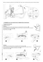
Sbloccare il motoriduttore (vedi SBLOCCO DEL MOTORIDUTTORE), fissare il braccio condotto alla staffa cancello come indicato nel disegno. Pag. 9 - Codice manuale: FA00095-IT - ver. 4 - 08/2017 - © Came S.p.A. - I contenuti del manuale sono da ritenersi suscettibili di modifica in qualsiasi momento senza obbligo di preavviso ATTENZIONE! Se non ci sono le battute d’arresto, è obbligatorio fissare i fermi meccanici. Fissaggio dei fermi meccanici Sbloccare il motoriduttore. In apertura. Aprire completamente l’anta. Fare un segno sulla cassa in corrispondenza del centro del braccio (). Chiudere manualmente...
Open the catalog to page 9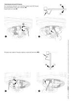
Determinazione dei punti di finecorsa Con il motoriduttore sbloccato e con l’anta chiusa, regolare il grano del finecorsa di chiusura girandolo in senso orario o antiorario (). Fissare il grano con il dado (). Allo stesso modo, regolare il finecorsa di apertura sul grano dell’altro fermo (). Pag. 10 - Codice manuale: FA00095-IT - ver. 4 - 08/2017 - © Came S.p.A. - I contenuti del manuale sono da ritenersi suscettibili di modifica in qualsiasi momento senza obbligo di preavviso
Open the catalog to page 10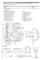
A Attenzione! Prima di intervenire sul quadro comando, togliere la tensione di linea e, se presenti, scollegare le batterie. Tutte le connessioni sono protette da fusibili rapidi. Descrizione delle parti 1. Morsettiera per dispositivi di segnalazione 2. Morsettiere per motoriduttori con encoder 3. Morsettiera per dispositivi di comando 4. Morsettiera per dispositivi di sicurezza 6. Morsettiera per selettore a tastiera 7. Morsettiera per dispositivi a transponder 9. Connettore per modulo CONNECT GW 12. Connettore per scheda Memory Roll 15. Connettore per scheda RIO-CONN 22. Alloggiamento per modulo...
Open the catalog to page 11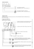
Uscita segnalazione cancello aperto. (Portata contatto 24 V AC/DC - 3 W max). Vedi funzione F 10. Uscita collegamento lampeggiatore o lampada ciclo. (Portata contatto: 24 V AC/DC - 25 W max). Vedi funzione F 18. ATTENZIONE! Prima di inserire una qualsiasi scheda a innesto (es.: AF, R800) e OBBLIGATORIO TOGLIERE LA TENSIONE DI LINEA e, se presenti, scollegare le batterie. Connettore per modulo CONNECT GW. ffl CONNECT GW non funziona se viene collegato il modulo RGP1 o la scheda RSE. Connettore per scheda R700 (per l'utilizzo del transponder o del lettore tessere) o per scheda R800 (per l'utilizzo...
Open the catalog to page 12All CAME S.P.A catalogs and technical brochures
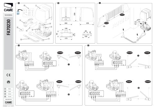 FA00096M4A
2 Pages
 SWING-GATE OPERATOR
96 Pages
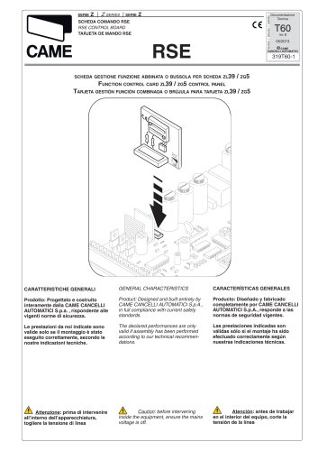 RSE
RSE24 Pages
- Security bollard
- Public space bollard
- Industrial barrier
- Metal bollard
- Door intercom
- Industrial thermostat
- Metal barrier
- Public space barrier
- Outdoor bollard
- White thermostat
- Programmable thermostat
- Heating thermostat
- Digital thermostat
- Wall-mounted thermostat
- Industrial turnstile
- Commercial turnstile
- Thermostat with digital display
- Stainless steel bollard
- Room thermostat