


- Products
- Catalogs
- News & Trends
- Exhibitions
D 45 technical guide

D 45 technical guide
- Uses CAT5 cables for easy installation and cost savings.
- Separate transmission of audio and video signals for improved performance.
- Automatic video signal equalization and amplification for high-quality video over long distances.
- Smart power supply management for energy efficiency.
- Embedded operating system for enhanced operation efficiency and display quality.
- Supports various system sizes and configurations.
- Long-distance video signal transmission without amplifiers.
- Two management center levels: district and system.
- Entrance Panels: Digital Colour and Small Colour models with varying dimensions and power requirements.
- Handsets: Available in Colour Handsfree, B/W, and Audio models with different screen sizes and power consumption.
- Accessories: Include Floor Shunt, Riser Shunt, Video Splitter, Video Mixer, District Generator, and more, each with specific installation and power details.
- Power Supply: Wall-mounted units with AC input and DC output specifications.
- Installation rules and wiring diagrams are provided for proper setup.
- Configuration involves setting parameters such as entrance panel address, floor quantity, and maximum internal units per floor.
- System supports multiple entrance panels with sequential addressing for monitoring and communication.
- Volume adjustment, blue backlight, and LCD display for user guidance.
- Address book download and direct call capabilities.
- Anti-removal alarm and adjustable CCD camera.
- Software updates without opening the device cover.
- Automatic alarm for overtime door opening and distress code alerts.
- Door lock release via password with configurable settings.
- Alarm for overtime door opening and distress code entry.
- Master password recovery and function setting options.
- Time Delay After Alarm Set: Configurable delays (40s to 255s) with corresponding LED indicators. Default is 100s for thief area alarms.
- Time Delay After Alarm Happens: Similar delay settings as above, with a default of 40s.
- Sound Alarm for Thief: Can be enabled or disabled. Default is no sound.
- Doorbell Function: Can be enabled or disabled. Default is disabled, using Small EP function instead.
- Handset Connection: Indicates connection status to the apartment interface. Default is not connected.
- Small EP Short Circuit: Causes handset to emit 3 short beeps and enter standby.
- Overload or Short Circuit: Handset supplies 12V DC to sensors, max 300mA. Overload triggers an alarm message.
- Alarm Zone Enablement: Requires correct sensor connection and configuration.
- Small EP Installation: Connect to master IU when multiple IUs are present.
- Electric Door Lock: Requires item 323015 for door lock release function.
- SOS External Switch: Sends SOS alarm message to switchboard when activated.
- Setup Operations: Inactivity or incorrect input results in 3 short beeps and return to standby.
- Household Number Setup: Configurable from 101 to 9999, with specific setup procedures.
- Number of Households per Floor: Configurable from 1 to 99, default is 4.
- SOS NO/NC Setup: Configurable SOS status with message light indicators.
- Master and Slave Handsets: Only one master per household, others set as slaves.
- Switchboard: Manages functions like password change, video parameter adjustment, and device type selection.
- Riser Shunt (323003): Connects riser BUS and system BUS, separates BUS, and switches between video and audio channels. It includes RJ45 connectors and video gain DIP switches for adjusting video transfer distance.
- Floor Shunt (323002): Connects apartment handsets to the BUS, distributing video signals to up to four handsets.
- Villa Shunt (323016): Connects villa handsets to the BUS, supporting up to four floor shunts and ensuring signal distribution over distances up to 200 meters.
- Configuration Methods: Three methods are available: physical configurators, COM connection to a PC, and pushbutton configuration.
- Video Gain Settings: DIP switch settings are provided for adjusting video gain based on distance and signal type (color or B/W).
- Power Configuration: Power sources must be configured according to software calculations to ensure proper operation of shunts.
- Ensure correct configuration of the riser shunt to maintain system functionality.
- Adjust video gain settings based on actual image requirements and signal conditions.
- Follow power configuration guidelines to avoid operational issues.
- Maximum distance for video signal transmission is 1000 meters for color systems and 2000 meters for B/W systems.
- Villa shunt can only be used for one villa, with a maximum distance of 50 meters between the shunt and handsets.
- Time Zone and Clock Mode: Options for selecting time zones and clock modes (Slave or Master) with default values available.
- Date Format: Configurable with a default option.
- IP Configuration: Dynamic or Fixed IP modes are available. Default IP address is 192.168.1.100, with subnet mask 255.255.255.0.
- Authentication: Default password is 12345, recommended for maintenance.
- UNIVOCAL CODE: Input a unique identification code (range 1-100000) into the IP interface.
- Ethernet Configuration: Choose between Dynamic IP (requires DHCP) or Fixed IP (manual configuration).
- Handset Configuration: Set base addresses for handsets and entrance panels, with default values available.
- Switchboard Configuration: Add management centre addresses, defaulted at 1, with sorting options for priority calling.
- 323019 Interface: Extends riser systems beyond 400 handsets, up to 800, with video gain adjustments for signal quality.
- 323005 and 323010: Two types of power supplies, with 323005 capable of supplying power to data communication cables and offering impedance matching.
- Protection Features: Both power supplies have short circuit protection and smart power supply capabilities.
- Use default values where applicable for ease of maintenance.
- Ensure no IP or address repetitions within the same system.
- Install power supplies in cool, well-ventilated areas and avoid parallel connections with other power supplies.
- Resistor Configurator: Three modes (1, 2, 3) are available, marked by the 14th bit. This method takes precedence over others.
- Pushbutton Method: Effective only when the resistor method is not used. Involves entering configuration status, selecting configurator number, confirming parameters, and setting additional parameters if necessary.
- Configuration Enquiry: Allows checking current configuration by entering enquiry status and reading configuration values.
- Resistor Configurator: Insert appropriate resistor, press S1 and S2 to restart for new configuration.
- Pushbutton Configuration: Set values using pushbuttons, invalid if resistor is connected.
- Computer Serial Port Configuration: Connect PC to EP/Switchboard shunt and download configuration parameters.
- Wiring Method 1: Used for downloading configuration information and updating programs. It involves inserting as per the arrow direction.
- Wiring Method 2: Reserved for firmware specialists to upgrade programs.
- Entrance Panels and Indoor Handsets: Recommended installation height is 120-125 cm for accessibility. Avoid positioning cameras towards light sources.
- System Cable: Use CAT5 original cables for optimal performance. Specifications include a resistance value of 180 ohm/km.
- Standard RJ45 Connections: Two standards (T568A and T568B) are available, but mixing them in the same installation is not recommended.
- Types of Power Supplies: System and auxiliary power supplies are available. The 323005 model can function as both, depending on the impedance switch setting.
- Power Supply Solutions: Different configurations are provided based on the presence of riser shunts and switchboards.
- Door Locks: Recommended to use Legrand/Ortronics connectors. Additional power supply is required if the current exceeds 1A (DC12V).
- Connection of the auxiliary power supply inside the riser is detailed with specific configurations for when the system bus requires auxiliary power.
- The document provides guidelines for connecting switchboards to the BUS system auxiliary power supply.
- The riser shunt is used to extend the maximum number of handsets from 400 to 800. Additional configuration is required if certain components like 323011 are present.
- Configuration can be set using SF2 software or a keyboard, with specific configuration bits defined for riser EP numbers, quantities, and switchboard numbers.
- Examples illustrate configurations for different numbers of floors and handsets per floor, using system configuration modes 1 and 2.
- Configuration procedures are provided for extending switchboards and main EPs using item 323018.
- Different configuration methods are available, including resistor, keyboard, and RS232 configurations.
- Examples demonstrate configurations for various switchboard and EP address ranges.
- Configuration methods include resistor, keyboard, and RS232 configurations for power supply management.
- Details are provided for configuring power supply address ranges, floor numbers, and handset addresses.
- Power supply management and smart power functions are explained, with recommendations for systems with standby batteries and alarm functions.
- All configurations must be numbered sequentially, starting from 1, with no numbers missed.
- Compatibility between D45 and BT 2-wire systems requires specific configurations, but is not necessary if compatibility is not required.
- Configuration errors are indicated by LED indicators, and specific steps are provided for correcting errors.
- Ensure correct configuration of power supply settings to avoid system malfunctions.
- Follow specific configuration examples for different system setups.
- Use suggested power solutions to prevent overloads and damage.
- Address troubleshooting steps for common issues to maintain system functionality.
- Riser Network: Examples include configurations without switchboards, with mixed installations, and with more than five entry points (EPs).
- Backbone Network: Configurations include a single main entrance panel, a single switchboard, and several main EPs. There is also a setup with a district generator.
- Internal Connections: Details on connecting internal units, audio and video handsets, and BTicino 2-wire interfaces.
- Basic Connections: Diagrams for basic handset connections and apartment interface connections.
- Riser Connections: Includes configurations with floor shunts and several EPs.
- Backbone Connections: Diagrams for connections with one main EP, one switchboard, and several EPs.
- District Generator: Connections for district generators and two-layer district generator setups.
- Video Mixers and Splitters: Configurations for risers with video mixers and two-branch video splitters.
- Alarm Sensors: Connections for internal unit alarm sensors, detailing the use of resistors for detecting cable issues.
- Handsets: Various configurations and power requirements, including the need for auxiliary power supplies when limits are exceeded.
- EPs: Main and secondary EPs are used in different configurations to manage entry points.
- Power Supply: Details on power consumption and the use of auxiliary power supplies.
Catalog excerpts

BTicino S.p.A. reserves at any time the right to modify the contents of this booklet and to communicate, in any form and modality, the changes brought to the same. BTicino SpA Via Messina, 38 20154 Milano - Italia www.bticino.com System technical guide
Open the catalog to page 1
D45 Video Door Entry System General features and devices overview. . . . . . . . . 02 Installation rules. . . . . . . . . . . . . . . . . . . . . . . 73 D45 VIDEO DOOR ENTRY SYSTEM Configuration concept and examples . . . . . . . . . 95 Troubleshooting. . . . . . . . . . . . . . . . . . . . . . 124 System topology - layout examples . . . . . . . . . . 127 Wiring diagrams. . . . . . . . . . . . . . . . . . . . . . 137
Open the catalog to page 3
CARATTERISTICHE GENERALI VIDEO DOOR ENTRY SYSTEM - GENERAL FEATURES D45 System introduction D45 VDE system consists of five main components: Entrance Panels, Internal Units (Handsets), Switchboard, system accessories, and Power Supply . It is a security monitoring system that applies MCU, serial connection BUS, TCP/IP LAN technologies. The system is designed to perform functions like call, doorbell, conversation, monitoring, door lock release, network, alarm, and message, by connecting riser systems with network system devices, and using the main Switchboard as the management and control centre...
Open the catalog to page 4
Products list and main features Model name code number Current absorption Standby SMALL COLOUR ENTRANCE PANEL Wall mount Wall mount Wall mount Wall mount AUDIO HANDSET Wall mount Wall mount FLOOR SHUNT RISER SHUNT 2 BRANCHES VIDEO SPLITTER ENTRANCE PANEL VIDEO MIXER DISTRICT GENERATOR BASIC APARTMENT INTERFACE POWER SUPPLY Wall mount AUXILIARY POWER SUPPLY Wall mount APARTMENT INTERFACE EP/SWITCHBOARD SHUNT VILLA SHUNT DOOR LOCK ACCESSORY CONFIGURATION TOOL WITH SOFTWARE D45 VIDEO DOOR ENTRY SYSTEM DIGITAL COLOUR ENTRAL PANEL ENTRANCE PANELS
Open the catalog to page 5
CARATTERISTICHE GENERALI VIDEO DOOR ENTRY SYSTEM - GENERAL FEATURES Entrance panel functions overview 322010 - Digital entrance panel colour With alloy-die-casting panel with luxurious and elegant appearance. The touchtone keyboard, stable in function, for direct handset call and communication. With a blue night-light display. Features Functions such as monitoring, call, conversation, door lock release, etc. n Volume adjustment; n Blue backlight and LCD display to guide user operation n Download the address book; n The visitor can call the handset and the Switchboard; n Anti-removal alarm; n...
Open the catalog to page 6
D45 VIDEO DOOR ENTRY SYSTEM LEGEND 1. Compensation Lamp 2. Confirm menu setting or other operation 3. Number keyboard: call the handset and function setting 4. Management centre pushbutton: call the Switchboard 5. Microphone 6. Photosensitive lamp 7. Return or quit menu setting 8. Alphanumerical pushbuttons 9. Access control lens (Optional) 10. Loudspeaker 11. Camera: to view the image 12. NN #FF #II: configurator 13. ISP: entrance panel software upgrade connector 14. SPK: adjust loudspeaker volume 15. MIC: adjust microphone volume 16. VIDEO-IN/GND/NC/+12V/LED-: connect entrance panel camera...
Open the catalog to page 7
CARATTERISTICHE GENERALI VIDEO DOOR ENTRY SYSTEM - GENERAL FEATURES Entrance panel functions overview 322010 DIGITAL EP Call by the visitors 1. A visitor can input the resident’s number as per the prompt on the display and press the # key for confirmation. The unit shall send out the call signal, displaying the message “calling, please wait” . It can establish two-way communication and at the same time transmit the image to the handset. Now the resident can open the lock by pressing the door lock release key on the handset. While waiting or during the conversation, the visitor can hang up the...
Open the catalog to page 8
Alarm for the dISTress code When the six-digit user password is entered for unlocking, and if the user re-enter the distress code “5” and presses the key for confirmation, then the entry panel shall send the distress code alarm to the Switchboard while it opens the lock. Open the locks by password As per the prompt on the display, we can input the unlock password after pressing on the # key. By pressing the same key again, the electric lock will be opened automatically. If the password input is not correct, the display will show “wrong password” and return to idle after three short beeps. Now...
Open the catalog to page 9
CARATTERISTICHE GENERALI VIDEO DOOR ENTRY SYSTEM - GENERAL FEATURES Entrance panel functions overview 322010 DIGITAL EP Set the Functions When used as (Backbone EP or main EP): Press the # key for about 5 seconds. Input the master password as per the prompt on the display and press the # key for confirmation. When you get to the setting status, you can enter the following settings as per the prompt: (Press on the 0 key to scroll through the pages). 1. Select 1 and change the master password. The default master password is 200000. If you want to change it, you can input your desired password as...
Open the catalog to page 10
Mode 7: 88-888-88-8888 88 Zone number 888 Building number 88 Unit number 88 Floor number 88 Room number Mode 8: 88-888-88-88A 88 888 88 88 A Zone number Building number Unit number Floor number Room number 9. Select 9 to complete the relevant settings of the password door lock release function. There are three available options: • Set the door lock release password. Press the 1 key and enter your desired group number and the password. On entering the group number, if password of the group already exist, it will be replaced by the new one. Press * key to exit and return to the last operation....
Open the catalog to page 11
CARATTERISTICHE GENERALI VIDEO DOOR ENTRY SYSTEM - GENERAL FEATURES Entrance panel functions overview Configure the EP Parameters The configuration parameters for the EP can be set either through Item 5 in the function settings under the LCD interface, or by means of the configurator. The latter is of high priority, but it will need repowering each time the resistance is replaced, as can be shown in the following diagram: NN refers to the EP address, #FF refers to the floor number and #II refers to the maximum number of rooms in each floor. It can download or update the software through the ISP...
Open the catalog to page 12All Bticino catalogs and technical brochures
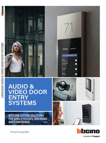 AUDIO & VIDEO DOOR ENTRY SYSTEMS
152 Pages
 Energy Data Logger
1 Page
 D45 System
7 Pages
 LINEA 100
2 Pages
 LINEA 300
2 Pages
 SOLIDA
12 Pages
 XCP
XCP108 Pages
 LIVING NOW
134 Pages
 Classe 100
32 Pages
 364232
2 Pages
 BUSBAR SYSTEM
166 Pages
 HOMETOUCH
8 Pages
 Hotel Room Management
16 Pages
 MEGASWITCH Disconnectors
6 Pages
 CLASSE 300
32 Pages
 AXIAL SWITCH
4 Pages
 New TV SOCKETS
8 Pages
 MÀTIX
MÀTIX40 Pages
 AIR
AIR28 Pages
 CES_2015_ZIGBEE_gb
2 Pages
 D45_brochure_GB
28 Pages
 GENERAL CATALOGUE
202 Pages
 video door entry sYstem offer
72 Pages
 Livinglight - Catalogue 2014
156 Pages
 My HOME FLATWALL
44 Pages
 Màtix - Catalogue 2014
82 Pages
 Axolute - Catalogue 2014
156 Pages
 My home complete guide
1152 Pages
 Telephone system technical guide
72 Pages
 Easy and flexible solutions
32 Pages
 D45 catalogue
14 Pages
 New audio solution
8 Pages
 Transcoding
4 Pages
 Sfera catalogue
16 Pages
 Classe 100 Catalogue
4 Pages


- Light fixture
- Industrial LED light
- Metal light fixture
- Commercial light fixture
- Contemporary light fixture
- Linear light fixture
- White light fixture
- Surface-mounted light fixture
- IP20 light fixture
- Plastic light fixture
- Single light fixture
- Home light fixture
- Black light fixture
- Contemporary switch
- Recessed switch
- Industrial socket
- Square switch
- Contemporary socket
- Industrial plug socket