


- Products
- Catalogs
- News & Trends
- Exhibitions
BUSBAR SYSTEM

BUSBAR SYSTEM
The document provides a comprehensive overview of Legrand's busbar systems, which are modern solutions for energy distribution in various building types. These systems are categorized into Low Power, Medium Power, and High Power ranges, catering to different installation requirements from 25 A to over 6300 A.
The busbars are designed to comply with product standards, ensuring rated current at an average room temperature of 40°C. Technical tables are available to verify voltage drop and overcurrent protection. The busbars are tested in certified LOVAG laboratories, ensuring compliance with safety and performance standards.
Busbars offer decentralized protection with junction boxes containing protection devices. They use minimal insulating plastic, which is self-extinguishing and halogen-free, reducing fire hazards. The metal casing acts as a shield, minimizing electromagnetic emissions, making them suitable for sensitive environments like hospitals and data centers.
Busbars provide high flexibility with outlet windows for easy system management and adaptation to changing needs. They allow for quick installation and changes without downtime, offering a single power distribution system that can be easily modified.
Busbars are lighter and more compact than traditional cable systems, requiring fewer supporting frames and allowing for quick installation. They offer reduced dimensions, especially for high-current applications, and allow for efficient use of space with 90° directional changes.
Legrand implements a strict Quality Management System, certified by Bureau Veritas, ensuring compliance with UNI EN ISO 9001 standards. The test labs, accredited by ACAE, conduct various tests to ensure product quality and compliance with standards.
Busbars have obtained various certifications, including LOVAG-ACAE approval, ensuring compliance with international standards. The Super-Compact line has received type-approval certifications for fire resistance and other quality tests.
Legrand's system concept allows for integration between busbar trunking systems, transformers, and cabinets, ensuring safety and performance through system approval certifications.
The LBplus range is designed for energy and lighting distribution, available in two versions with different profiles. It offers IP55 protection and common accessories for rationalization. The range includes new plugs for easy installation and maximum security.
The document provides detailed technical specifications and installation guidelines for the LBplus busbar trunking system, designed for power distribution in various sectors including service, advanced service, and manufacturing industries. It highlights the system's flexibility, ease of installation, and compliance with CEI EN 61439-6 standards.
The LBplus system is available in two types, A and B, with different dimensions and features. It offers IP55 protection, suitable for false ceiling and raised floor installations. The system supports both single-phase and three-phase devices, with rated currents ranging from 25A to 63A and operational voltages up to 400V.
Key components include straight lengths, feed units, fixing supports, and plug-in units. Straight lengths are made of galvanized steel and include tap-off outlets. Feed units are available for different current ratings and include end covers for protection. Fixing supports allow for various suspension methods, maintaining IP55 protection.
The system is designed for quick installation with a single operation for electrical and mechanical connections. It supports various load types with specified mechanical load limits. Plug-in units are available for different load capacities and include safety features like phase selection and protective conductor connections.
Detailed technical data is provided for both LBplus Type A and B, including conductor numbers, dimensions, current ratings, voltage ratings, and resistance values. The document also includes tables for mechanical loads and voltage drop calculations.
The LBplus system supports energy-saving protocols like DALI and 1-10 V, reducing energy consumption and operating costs through automatic lighting management.
LBplus data ensures compliance with EU Directives on energy efficiency for both new and refurbished buildings.
The system reduces energy consumption and emissions of polluting gases. It emphasizes reducing existing consumption as a starting point for achieving environmental sustainability.
LBplus data maintains the same electrical and mechanical features as the standard range, distributing rated currents from 25 to 63A. It includes two specific conductors for lighting management systems.
New plugs are available for energy drawing and BUS connection, suitable for various controls and lighting management.
LBplus data integrates a BUS for lighting management, compatible with DALI and 1-10V protocols, offering flexibility and configuration options for different environments like offices and shopping centers.
The system supports rated currents of 25-63A, operational voltage of 400V, and complies with IEC 61439-6 standards. It offers IP55 protection and IK07 impact resistance.
Includes straight lengths, feed units, flexible joints, and tap-off plugs. The system is designed for easy installation and connection, with high-quality materials ensuring compliance with safety standards.
The MS range offers speed, simplicity, and flexibility in installation, with tap-off boxes for up to 16 DIN modules, and compliance with IEC 61439-6 standards. It is fire retardant according to EN 60332-3.
The document provides detailed technical specifications and installation guidelines for the Minisbarre (MS) range, designed for medium power distribution in various settings such as laboratories, small to medium companies, and warehouses. The MS range ensures safe and efficient power distribution with a variety of accessories and tap-off boxes.
The MS range includes straight elements, flexible joints, and tap-off boxes with capacities of 63A, 100A, and 160A. The components are made from galvanized steel and feature a degree of protection up to IP55. The system is compliant with IEC 61439-6 standards and is designed to maintain fire-resistant properties when installed correctly.
The document outlines various installation accessories such as 90° angles, T-type and X-type elements, and flexible angles for different capacities. It also includes details on vertical installation elements and the necessary components for maintaining IP55 protection.
Tap-off boxes are available in various configurations, including empty boxes with DIN rails and boxes with fuse carriers. They are designed to connect and energize loads up to 63A and can be inserted and removed while the busbar is energized.
The document provides detailed technical data on the MS range, including dimensions, rated current, operational voltage, and thermal limits. It also includes information on phase resistance, reactance, and impedance, as well as voltage drop calculations for distributed loads.
The MS range includes fire barrier kits for maintaining fire resistance in compliance with relevant standards. The components are designed to ensure electrical continuity and safety during installation and operation.
The Minisbarre (MS) range offers a comprehensive solution for medium power distribution with a focus on safety, efficiency, and compliance with international standards. The variety of components and accessories allows for flexible installation in various environments.
The document outlines the specifications for feed units and busbars used in power distribution systems. Feed units can connect copper cables up to 35 mm2 for 63/100A units and 70 mm2 for 160A units. The MR (Medium Rating) range supports power distribution from 160A to 1000A using aluminum or copper conductors, compliant with IEC 61439-6 standards, and operates at a reference temperature of 40°C.
Installation involves using a monobloc system with a dynamometric nut for quick and reliable connections. The system is designed for easy installation and maintenance-free operation. In case of future interventions, the monobloc can be retightened using a torque wrench.
The MR line complies with IEC 61439-6 and has a protection degree of IP55. It also meets fire resistance standards (S120 and E120 according to IEC EN 1366) and passes the glow-wire test (IEC EN61439-6).
The MR range is recommended for use in industries, skyscrapers, hospitals, data centers, and shopping centers. It is particularly advantageous for vertical applications as it does not require busbar blocking or thermal expansion elements.
The MR busbars are known for their speed, simplicity, and flexibility in installation. They are made from high-quality materials ensuring sturdiness and functionality. The system is designed to compensate for thermal expansion, eliminating the need for additional expansion elements.
The system includes various components such as tap-off boxes, elbows, and straight elements with fire barriers. Tap-off boxes are available from 16A to 1000A and can house protection devices. The document also details the dimensions and weights of different components.
Tables in the document provide detailed specifications for straight elements, including their dimensions, weight, and current ratings for both aluminum and copper conductors. The tables also specify the number of windows for tap-off outlets and the protection degree for different applications.
The document provides detailed specifications for busbar trunking systems, including protective conductor resistance and reactance, fault loop resistance and reactance, voltage drop under various power factors, Joule effect losses, fire load, weight, and dimensions. The protection degree is IP55, and mechanical resistance is IK10. The busbars are fire retardant and comply with IEC standards.
The MR straight elements feature galvanized steel casings, multiple conductor configurations, fiberglass reinforced plastic insulators, and tap-off outlets. The system includes a monobloc electric junction system for reliable connections and is fire retardant according to IEC standards.
Feed units allow electrical power supply through cable lines or distribution boards, with options for center or end feed units. End covers ensure IP55 protection at the line's end.
Bracket supports or vertical suspension supports are necessary for fixing the line to building structures.
Tap-off boxes are used for energizing three-phase loads, with plug-in and bolted options available. They feature integrated disconnection devices, padlocking capabilities, and compliance with IEC standards.
Guidelines for designing rising mains include using specific feed units, suspension brackets, and straight elements with fire barriers. Installation instructions emphasize maintaining IP55 protection and proper measurement techniques.
The TS/MTS range is designed for moving users like cranes and assembly lines, featuring quick installation, high-quality materials, and compliance with IEC standards. It includes straight and curved elements, expansion joints, and various accessories for versatile applications.
The document emphasizes compliance with IEC 61439-6 and other relevant standards, ensuring fire retardancy and suitability for various environmental conditions.
The document outlines the specifications for busbar trunking systems, including insulation, fire resistance, and material properties. The insulation between bars is ensured by a double sheath made with polyester film, with thermal resistance options available. All plastic components are fire retardant and comply with UL94 standards.
The document provides detailed listings of straight elements for transport and distribution, specifying the product codes, current ratings (Aluminium and Copper), and lengths available. It includes configurations for different current ratings and lengths, with options for special requests.
Fire barrier elements are necessary for installations crossing fire-resistant walls or ceilings. The document specifies the dimensions and types of fire barriers required for different current ratings and materials (Aluminium and Copper).
Expansion elements are used to accommodate thermal expansion in busbar systems. The document specifies the conditions under which these elements are necessary and provides product codes for different configurations.
The document describes elements for phase balancing and inversion, which are used to manage phase sequence and impedance in long busbar sections. It provides guidelines for installation and product codes for various configurations.
Feed units are used at the end of busbar lines for power supply connections. The document details the dimensions, configurations, and product codes for different current ratings and materials.
The document includes specifications for elbows and special elements, with dimensions and configurations for both single and double bar systems.
The document provides detailed specifications and configurations for various types of elbows and T-elements used in electrical busbar systems. These components are essential for creating directional changes in busbar layouts, accommodating different installation requirements.
Horizontal elbows are categorized into two types based on the orientation of the neutral busbar conductor. Type 1 is a right horizontal elbow, and Type 2 is a left horizontal elbow. The document specifies that for non-standard horizontal elbows, only one side can exceed 600 mm in size. Standard dimensions for single and double bars are provided, with variations depending on the current rating.
Vertical elbows are also divided into two types, with Type 1 having the neutral on the left and Type 2 on the right. The document outlines the dimensions for standard elements and specifies that non-standard vertical elbows can have only one side exceeding 600 mm.
Double elbows combine two horizontal or vertical elbows. The document describes the configurations for double horizontal and vertical elbows, specifying the types based on the sequence of left and right elbows. Dimensions for single and double bars are provided, with specific limits for non-standard elements.
These elbows combine a horizontal and a vertical elbow. Four types are defined based on the combination of right and left orientations. The document provides dimensions and specifies that only one side can exceed 600 mm for non-standard elements.
Similar to the horizontal + vertical combination, these elbows are defined by four types based on orientation. Dimensions and non-standard element specifications are provided.
T-elements are used to split the line into two branches. The document describes four types of vertical T-elements, providing dimensions for standard elements and specifying conditions for non-standard elements.
The document includes notes on the right (RH) and left (LH) orientations and provides guidelines for ordering non-standard elements, emphasizing the importance of adhering to specified dimensions.
This document provides technical specifications and configurations for single and double bar systems, horizontal T elements, and various connection interfaces with exit bars. It includes details on dimensions, types, and ratings for different configurations.
- Single bar minimum/maximum dimensions: 600/1449 mm for types A, B, and C.
- Double bar minimum/maximum dimensions: 600/1449 mm for types A, B, and C.
- Used to split lines into two branches, combining effects of diverging elbows.
- Four types available, each with dimensions A, B, and C.
- Standard dimensions for single/double bar (A+B+C): 600+600+600 mm.
- Non-standard elements allow one side to exceed 600 mm.
- Standard and special connection interfaces available for right and left configurations.
- Standard dimensions for single/double bar (U+A): 200+300 mm.
- Non-standard elements allow one side to exceed specified dimensions.
- Includes configurations with horizontal and vertical elbows.
- Dimensions vary based on type and rating, specified in technical information.
- Single bar ratings: 630A-2000A (Al), 800A-2500A (Cu).
- Double bar ratings: 2500A-4000A (Al), 3200A-5000A (Cu).
- Detailed drilling specifications for coverplates and bars provided.
- Dimensions change with rating, specified in technical information.
The document provides technical specifications and installation guidelines for Super Compact (SCP) tap-off boxes, which are bolt-on type boxes used for power distribution from busbars. These boxes are available in two types, Type 4 and Type 5, with current ratings ranging from 125A to 1250A.
- Type 4 boxes come with an AC23 switch disconnector and fuse carrier, available in ratings from 125A to 1250A.
- Type 5 boxes are empty and available in the same current ratings.
- Rated insulating AC voltage is 1000V, with an impulse withstand voltage of 12kV.
- Conforms to CEI EN 60947-3 standards.
- Tap-off boxes must be installed when the busbar is disconnected and not energized.
- Boxes cannot be installed simultaneously on both sides of the same junction.
- For operating voltages different from 400V, contact Legrand.
- Fuses are not included and should be referred to in the general Legrand catalogue.
- Type 4 and Type 5 boxes have specific dimensions for different current ratings, detailed in tables within the document.
- Terminal dimensions and cable input specifications are provided for each type.
- Suspension brackets are available for both edgewise and flat installations, with specific recommendations for installation distances.
- Brackets are certified for various environments, including seismic and naval applications.
- End covers and protective bellows are available for ensuring IP55 protection and for outdoor applications.
- Diagrams illustrate the installation of tap-off boxes in different configurations and environments.
- Specific instructions are provided for designing riser mains and using suspension brackets.
The document outlines various specifications for cable glands and fuses, including dimensions and operating features. It specifies the use of ceramic fuses with a breaking capacity of 1500A and a voltage drop of 150 mV. The document also references the LEGRAND catalogue for selecting cable glands and fuses.
Guidelines are provided for choosing cable glands and fuses, emphasizing the importance of referring to the LEGRAND catalogue. The document includes a comparison table for plug-in boxes and cable glands, detailing the maximum number of cable glands that can be installed using appropriate flanges.
The document provides detailed calculations for Joule effect losses in busbars, overload protection, and voltage drop in busbar trunking systems. It explains the formulas for calculating power loss, overload protection conditions, and voltage drop, considering factors like current distribution and ambient temperature.
Information is provided on short circuit withstand capabilities, including the calculation of estimated short circuit currents and the selection of protection devices. The document details the factors affecting short circuit current intensity and provides formulas for calculating short circuit impedance and current.
The document discusses the impact of harmonics on distribution systems, highlighting issues such as power factor deterioration, heating of the Neutral, and additional losses in electric machinery. It provides guidance on choosing the appropriate rating for busbars in the presence of harmonics, using Total Harmonic Distortion (THD) as a measure.
The document includes several tables, such as the comparison table for plug-in boxes and cable glands, and tables for calculating voltage drop and short circuit currents. These tables provide critical data for selecting and sizing components in electrical systems.
The document outlines the rated current capacities for SCP busbars, ranging from 630 A to 5000 A, and specifies the conditions under which different busbars should be used based on Total Harmonic Distortion (THD) levels. It emphasizes the importance of measuring harmonic distortion using a network analyzer.
The document details the degrees of protection against mechanical impact (IK) and intrusion (IP) as per IEC standards. It explains the protection levels against solid bodies and liquids, with specific IP ratings indicating the degree of protection.
Legrand's busbar trunking systems are designed to minimize electromagnetic emissions. The document discusses the measurement of magnetic induction, highlighting that emissions are significantly lower than those from cables with similar current intensity. It mentions legislative standards for exposure limits and the importance of low magnetic emissions for international markets.
The document provides detailed procedures for assembly checks before operation, including checks on junctions and connections to control panels. It outlines the necessary torque values for connection screws and the importance of electric safety tests. Regular checks are recommended after the first year of operation and every two years thereafter, focusing on thermal measurements and the integrity of insulating materials.
The document includes tables comparing magnetic induction levels from various household and industrial equipment, emphasizing the low emissions from SCP busbars. Graphs illustrate the magnetic induction near busbar junctions, showing compliance with legislative quality objectives.
1. Ensure the Monobloc is dry and free from any residues using hot air (max 80°C) and bland reactants like trichloroethylene.
2. Verify correct adhesion of the Monobloc to busbar conductors using a 0.05 mm feeler if necessary.
3. Check the torque of self-shearing bolts with a torque wrench calibrated at 85 Nm at ambient temperature.
4. Conduct insulation tests at 1000 V with a minimum value of 100 MOhm for each insulated section. If unsuccessful, identify and replace faulty sections.
1. Perform annual thermal checks on the cover near the lock using thermal sensors or pyrometers.
2. Record temperature values along with ambient temperature and operating current.
3. If temperature deviation exceeds 55 K or deviates more than 15 K from initial checks, contact technical support.
4. Verify connection screws for correct torque (85 Nm).
1. Flexibility of SCP line allows customization for specific requirements like continuous current systems or stainless steel casing.
2. Special requirements include 200% neutral, 5 conductor version, customized color painting, and more.
3. Example system path provided with measurements for ordering completion items.
1. Installation in 2013 with 3 floors and 54 total busbar lines.
2. 6 lines (SCP 3200A Al – 3P+N – IP55) for power supply, 48 lines (MR 400A Al – 3P+N – IP40) for distribution.
3. Utilization of SCP PLUG-IN BOX 630A SWITCH DPX and MRF PLUG-IN BOX 63A EMPTY.
1. LB PLUS and MINISBARRE systems for light and medium power distribution.
2. Company reserves the right to change specifications and designs without notice.
Catalog excerpts

BUSBAR SYSTEM SOLUTIONS FOR THE ELECTRICAL DISTRIBUTION BUSBAR SYSTEM In accordance with its policy of continuous improvement, the Company reserves the right to change specifications and designs without notice. All illustrations, descriptions, dimensions and weights in this catalogue are for guidance and cannot be held binding on the Company. GLOBAL SPECIALIST IN ELECTRICAL AND DIGITAL BUILDING INFRASTRUCTURES
Open the catalog to page 1
LB PLUS BUSBAR FROM 25, 40 TO 63 A Light and Power. The solution that comes from above page 12 LB PLUS DATA BUSBAR FROM 25, 40 TO 63 A The new busbar trunking system for LIGHTING MANAGEMENT page 26 MINISBARRE (MS) BUSBAR FROM 63, 100 AND 160 A The compact solution for medium power distribution page 32
Open the catalog to page 2
MEDIUM RATING (MR) BUSBAR FROM 160 TO 1000 A Performance and functionality in medium power page 42 TROLLEY SYSTEM (TS-MTS) BUSBAR FROM 63 TO 250 A Every time when the power required is on the move page 74 SUPER COMPACT (SCP) BUSBAR FROM 630 TO 6300 A The power solutions for industrial and service sector applications page 86
Open the catalog to page 3
The busbar is the most modern solution for the distribution of energy in an installation for machinery, equipment and lighting fittings, in all types of buildings such as warehouses, trade fairs. The busbar is also frequently used to power the (horizontal and vertical) backbones of buildings used for the commercial-service sectors, thus observing the time required for the installation and providing a final solution with remarkable technical advantages. Legrand’s busbars, available in 3 segmented ranges (Low Power, Medium Power and High Power), are able to meet all installation requirements, from...
Open the catalog to page 4
Easy The electric design of the busbars is achieved in compliance with the product Standards. The rated current of our busbars is guaranteed at a room average temperature of 40 °C (n.d.r. the Standard requires 35°C). After choosing the busbar which is able to meet the operating current regulations, it will be very easy to verify the voltage drop as well as the protection against overcurrents by using the technical tables available for all our production lines. In particular, these tables define a wide range of technical data which allow the planning engineer to carry out calculations with electric...
Open the catalog to page 5
ADVANTAGE Flexibility By using the outlet windows located on the straight elements, the busbars provide high management flexibility, both when planning (electrical engineer) and when installing the system (installer); they are also used for the unavoidable changes required by the electric system to adapt to the varied needs of the end user during the life of plant. The junction boxes can be inserted and removed from their outlets when the busbar is electrically powered and inserted in another plug outlet, thus avoiding downtime. Example of lighting and small power distribution The engineering...
Open the catalog to page 6
Quick installation The busbar’s junction and fixing systems have been designed and created to install busbars easily. In a cable and tray system, the time required to install only the tray is the same used to install a complete system in busbars. Furthermore, given the same capacity, a power busbar, which generally has aluminium conductors, is much lighter than a system made with (copper) cables: lighter weights require a lower number of supporting frames or, in any case, more simple and inexpensive supporting frames. That is why the installation time of a busbar is obviously shorter than a similar...
Open the catalog to page 7
Company approval CERTIFICATIONS The quality management system Legrand has always considered Quality one of the strategic points of its policy, and therefore implements a strict Quality Management System. The efficacy of the procedures devised and the level of organisation required for their implementation, have enabled the company to obtain the approval certification of its Quality Management System in accordance with the latest edition of the UNI EN ISO 9001 standard. All company processes, from Marketing to Product Development, Manufacturing, Sale, and Technical Support, contribute to meeting...
Open the catalog to page 8
0 legrand Mark certifications and approvals Once compliance with IEC 61439-6 product standard has been confirmed, the various product lines may be further marked and approved for special applications. The compliance of a product to the specific standards can be certified by the manufacturer declaration and the application of the "CE" symbol, or through the concession of a mark by an appointed third party body that ascertains its compliance. In the case of manufacturer declaration, the responsibility for compliance with the standards lies with the manufacturer itself; If a quality mark is granted...
Open the catalog to page 9
The CERTIFICATES The Super-Compact tine has been given Type- Approval Certifications by the most prestigious Electro-technical agencies: Certificate of Compliance with Standard: 61439-6 (ACAE - LOVAG) EAC Type-Approval (Russia) In order to obtain these recognitions, the SCP range has undergone the following type tests, as confirmation of their quality: EI 120 fire resistance with Fire Barrier IEC 60331-1 / CEI EN 50362 - Fire Resisting Test BUSBARS TRUNKING SYSTEM HV/LV CAST RESIN TRANSFORMERS
Open the catalog to page 10
Group synergy allows for immediate integration between Thanks to a reinforcement kit it is possible to quickly and easily busbar trunking systems, cast resin transformers and Legrand install any kind of board connection to the roof of the cabinet. XL³ cabinets. The safety and the performance of the Legrand system are Cast resin transformers can be made to order with a preguaranteed by the system approval certification, obtained installed interface connection for the busbar trunking systems. following stringent tests carried out in the most important international labs. The cabinets XL3 can be...
Open the catalog to page 11
BUSBAR FROM 25, 40 TO 63 ALight and Power. The solution that comes from above LBplus is the range of busbars for the distribution of energy and lighting from 25 to 63 A. With LBplus, it is possible to have busbars with 10. 16, and 25 A Plugs, with a reduction of the codes of the range, increasing functionality, thanks to accessories suitable for all the versions. With LBplus the line becomes extremely flexible, with the possible to adapt the system to any development. LBplus has been conceived for the distribution of energy and lighting, all in one product. The main features are: 2 PRODUCT SPECIFICATIONS...
Open the catalog to page 12All Bticino catalogs and technical brochures
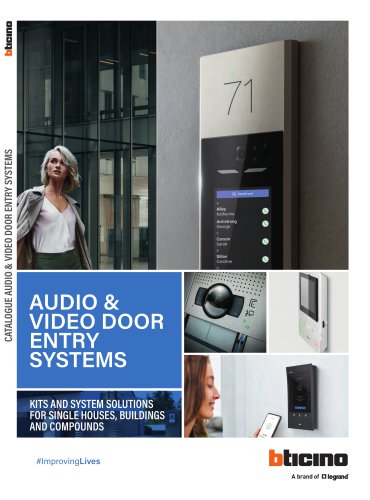 AUDIO & VIDEO DOOR ENTRY SYSTEMS
152 Pages
 Energy Data Logger
1 Page
 D45 System
7 Pages
 LINEA 100
2 Pages
 LINEA 300
2 Pages
 SOLIDA
12 Pages
 XCP
XCP108 Pages
 LIVING NOW
134 Pages
 Classe 100
32 Pages
 364232
2 Pages
 HOMETOUCH
8 Pages
 Hotel Room Management
16 Pages
 MEGASWITCH Disconnectors
6 Pages
 CLASSE 300
32 Pages
 AXIAL SWITCH
4 Pages
 New TV SOCKETS
8 Pages
 MÀTIX
MÀTIX40 Pages
 AIR
AIR28 Pages
 CES_2015_ZIGBEE_gb
2 Pages
 D45_brochure_GB
28 Pages
 GENERAL CATALOGUE
202 Pages
 video door entry sYstem offer
72 Pages
 Livinglight - Catalogue 2014
156 Pages
 My HOME FLATWALL
44 Pages
 Màtix - Catalogue 2014
82 Pages
 Axolute - Catalogue 2014
156 Pages
 My home complete guide
1152 Pages
 Telephone system technical guide
72 Pages
 Easy and flexible solutions
32 Pages
 D 45 technical guide
156 Pages
 D45 catalogue
14 Pages
 New audio solution
8 Pages
 Transcoding
4 Pages
 Sfera catalogue
16 Pages
 Classe 100 Catalogue
4 Pages


- Light fixture
- Industrial LED light
- Metal light fixture
- Commercial light fixture
- Contemporary light fixture
- Linear light fixture
- White light fixture
- Surface-mounted light fixture
- IP20 light fixture
- Plastic light fixture
- Single light fixture
- Home light fixture
- Black light fixture
- Contemporary switch
- Recessed switch
- Industrial socket
- Square switch
- Contemporary socket
- Industrial plug socket