- Catalogs
- Bruag Design Factory AG
- A.5 Technical Sheet Balcony Acoustic Solution
- Company
- Products
- Catalogs
- News & Trends
- Exhibitions
A.5 Technical Sheet Balcony Acoustic Solution
1 /13Pages

A.5 Technical Sheet Balcony Acoustic Solution
1 /13Pages
Catalog excerpts
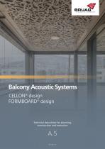
Balcony Acoustic Systems CELLON® design FORMBOARD® design Technical data sheet for planning, construction and execution
Open the catalog to page 1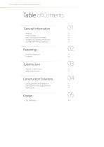
Technical data sheet | Balcony Acoustic Systems Table of Contents General Information Material Panel Formats Data Transmission for Orders Storage and Cleaning Instructions Cutting and Drilling Guidelines Fastenings Fastening Distances Fasteners Substructure Wooden Substructure Metal Substructure Construction Solutions Ceiling System with Shadowline Ceiling System with Edge Distance Wall System
Open the catalog to page 2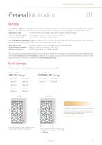
Technical data sheet | Balcony Acoustic Systems General Information Material Our CELLON® panel is a high-pressure laminate panel (HPL Compact or solid core panel) consisting of 70% cellulose webs and 30% phenolic resin. The extremely weather and frost-resistant material is ideal for outdoor applications. Application area: Panel thickness (weight): Reaction to fire class: mounted vertically in outdoor areas (e.g. facades, balcony railings) 8mm (approx. 12kg/m²), 10mm (approx. 15kg/m²) RF2, B1 (DIN 4102-1), B-s1-d0 (EN 13501-1) The FORMBOARD TOP PINE® panel is a high-density wood-based panel bonded...
Open the catalog to page 3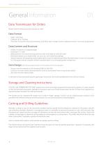
Technical data sheet | Balcony Acoustic Systems General Information Data Transmission for Orders Please note the following when placing an order: Data Format DWG / DXF Data Cadwork 2D or 3D Data Parts lists in Excel (if only as Excel without CAD file is sent, it might result in additional work in our work preparation) Data Content and Structure Panels are drawn on a separate layer Drawing in 1:1 ratio Measurement of at least one long and short side to be able to verify the scale Boreholes (drawn as a closed circle), cut-outs, etc. are marked accordingly Special requests for grouping and/or palletisation...
Open the catalog to page 4
Technical data sheet | Balcony Acoustic Systems Fastening Distances Single-span borehole Ø 8 mm can be drawn directly in DXF/DWG file d Maximum distance according to wind load qek (wind pressure or suction) CELLON® 8 mm FORMBOARD TOP PINE® 10 mm CELLON® 10 mm FORMBOARD TOP PINE® 18 mm 0.5 kN/m² Distance borehole to edge Horizontal borehole distance Vertical borehole distance Frame without perforation Reciprocal conversion: c (adjusted) = b (max) / b (effectiv) x c (max) b (adjusted) = c (max) / c (effectiv) x b (max) The values given are guidelines and do not release you from having an object-related...
Open the catalog to page 5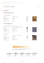
Technical data sheet | Balcony Acoustic Systems Fasteners Wooden Substrucure Truss-head Screw Stainless steel A2 38 mm 4.8 mm 12 mm TX20 8 mm Material: Length: Nominal diameter: Head diameter: Drives: Borehole diameter: Metal Substructure Truss-head Screw Material: Length: Nominal diameter: Head diameter: Drives: Borehole diameter: (self-drilling with sealing washer) Bi-metal (Stainless steel A2/Steel) 26 mm / 38 mm 5.5 mm 14 mm SIT® 25, TX 25 8 mm Blind Rivet Material: Length: Nominal diameter: Head diameter: Drives: Borehole diameter: Aluminium/Stainless steel A2 8-13 mm 5.0 mm 14 mm Blind...
Open the catalog to page 6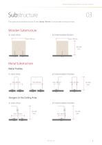
Technical data sheet | Balcony Acoustic Systems The substructure should be at least 50 mm, ideally 100 mm. It can be made in wood or metal. Wooden Substructure in Joint Area Metal Substructure Metal Profiles in Joint Area Hangers in the Ceiling Area in Joint Area
Open the catalog to page 7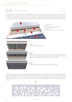
Technical data sheet | Balcony Acoustic Systems Perforated panels made of CELLON® or FORMBOARD TOP PINE® can be used to create visually unique acoustic structures. The perforation should have an open area of at least 40% for optimal sound absorption. Behind the perforated panel is a fleece and a 30 mm thick sound absorber. The air space above the absorber should be correspondingly 20 to 70mm, so that the low tones can be absorbed as best as possible. The larger the air space, the better these tones are absorbed. Concrete ceiling Cavity Construction frame in wood/metal Sound absorber (30 mm) Fleece...
Open the catalog to page 8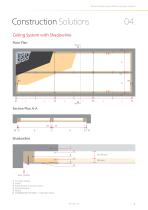
Technical data sheet | Balcony Acoustic Systems Construction Solutions Ceiling System with Shadowline Floor Plan Concrete ceiling Cavity Substructure in wood or metal Sound absorber Fleece FORMBOARD TOP PINE® or CELLON® Platte
Open the catalog to page 9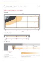
Technical data sheet | Balcony Acoustic Systems Construction Solutions Ceiling System with Edge Distance Floor Plan Concrete ceiling Cavity Substructure in wood or metal Sound absorber Fleece FORMBOARD TOP PINE® or CELLON® Platte Note In the case of rectangular surfaces, it is advisable to start with the structure on all sides approx. 100 mm from the edge. This makes planning and installation more efficient.
Open the catalog to page 10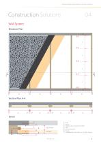
Technical data sheet | Balcony Acoustic Systems Construction Solutions Wall System Elevation Plan 25 8Ø c 8Ø Wall Cavity Substructure in wood or metal Strip Sound absorber Fleece FORMBOARD TOP PINE® or CELLON® Platte
Open the catalog to page 11
Technical data sheet | Balcony Acoustic Systems You can find the entire perforation collection in our catalogue.
Open the catalog to page 12
Bruag Design Factory AG Switzerland +41 71 414 00 90 [email protected] www.bruag.ch
Open the catalog to page 13All Bruag Design Factory AG catalogs and technical brochures
 Innovative Cladding Elements
25 Pages
 Ventilated Façade Solutions
9 Pages
 Noise-Virus-Catcher®
1 Page
 Zeitgeist 2016
2 Pages


Archived catalogs
 Acoustics Elements
3 Pages
 CELLON® design
8 Pages
 Zeitgeist 2015
4 Pages
 Brève Information CELLON®
2 Pages


- Bruag decorative panel
- Bruag cladding
- Industrial planter
- Exterior planter
- Industrial wallcovering
- Bruag interior decorative panel
- Modern planter
- Interior wall-covering
- Commercial decorative panel
- Bruag wall-mounted decorative panel
- Commercial planter
- Bruag panel cladding
- Bruag acoustic panel
- Cover decorative panel
- Public space planter
- Commercial wall-covering
- Fencing
- Industrial suspended ceiling
- Bruag commercial acoustic panel