
- Catalogs
- Bruag Design Factory AG
- A.3 Technical Sheet Balcony Balustrades


- Company
- Products
- Catalogs
- News & Trends
- Exhibitions
A.3 Technical Sheet Balcony Balustrades

A.3 Technical Sheet Balcony Balustrades
The CELLON® panels are high-pressure laminate panels ideal for outdoor applications such as facades and balcony railings. They are composed of 70% cellulose and 30% phenolic resin, offering excellent weather and frost resistance. Available in various raw widths and lengths, these panels can be customized to specific project dimensions using laser technology. The panels are tested for breakthrough safety and protection against overclimbing, adhering to ETB guidelines.
Fastenings
Fastening distances are specified for different mounting types, including top and front-mounted balcony railings. The document provides guidelines for borehole distances and joint sizes. Fasteners include truss-head screws made of bi-metal, with specific dimensions and installation instructions.
Substructure
The substructure must be calculated by a metal worker, considering regional structural and static regulations. The document provides example illustrations for balcony railing constructions, including top-mounted, front-mounted, and floor-to-ceiling window guardings with various profiles.
Corner & Transition Profiles
Recommendations are provided for corner connections and handrail variations, including the use of L-profiles to protect panel edges and ensure a clean finish.
Construction Solutions
Various construction solutions are illustrated, including top-mounted railings with handrails and front-mounted railings without handrails. Each solution includes elevation and section plans, along with visualization examples.
Design
The document references a catalogue for the complete collection of perforation designs available for CELLON® panels.
Additional Information
Storage and cleaning instructions emphasize the importance of protecting panels from water damage and using appropriate cleaning methods. Cutting and drilling guidelines suggest using carbide or diamond cutting tools and provide instructions for on-site processing if necessary.
Catalog excerpts
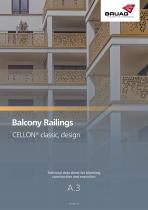
Balcony Railings CELLON® classic, design Technical data sheet for planning, construction and execution
Open the catalog to page 1
Technical data sheet | Balcony Railings Table of Contents General Information Material Panel Formats Data Transmission for Orders Storage and Cleaning Instructions Cutting and Drilling Guidelines Breakthrough Safety/Raliing Statics Protection against Overclimbing Fastenings Fastening Distances Fasteners Substructure Balcony Railing Top Mounted Balcony Railing Front Mounted Guarding Floor-to-Ceiling Window with Panel on Surrounding Square Tube Guarding Floor-to-Ceiling Window with Panel on Horizontal Square Tube Guarding Floor-to-Ceiling Window with Panel on Surrounding L-profile Corner & Transition...
Open the catalog to page 2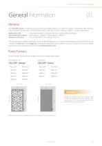
Technical data sheet | Balcony Railings General Information Material Our CELLON® panel is a high-pressure laminate panel (HPL Compact or solid core panel) consisting of 70% cellulose webs and 30% phenolic resin. The extremely weather and frost-resistant material is ideal for outdoor applications. Application area: Panel thickness (weight): Reaction to fire class: mounted vertically in outdoor areas (e.g. facades, balcony railings) 8mm (approx. 12kg/m²), 10mm (approx. 15kg/m²) RF2, B1 (DIN 4102-1), B-s1-d0 (EN 13501-1) The raw panels are project-specifically cut to the desired dimensions using...
Open the catalog to page 3
Technical data sheet | Balcony Railings General Information Data Transmission for Orders Please note the following when placing an order: Data Format DWG / DXF Data Cadwork 2D or 3D Data Parts lists in Excel (if only as Excel without CAD file is sent, it might result in additional work in our work preparation) Data Content and Structure Panels are drawn on a separate layer Drawing in 1:1 ratio Measurement of at least one long and short side to be able to verify the scale Boreholes (drawn as a closed circle), cut-outs, etc. are marked accordingly Special requests for grouping and/or palletisation...
Open the catalog to page 4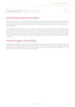
Technical data sheet | Balcony Railings General Information Breakthrough Safety/Raliing Statics Our CELLON® panels are to be considered as fillings and must meet the requirements for breakthrough safety. The perforations from the balcony design collection are tested in accordance with the ETB guidelines “Components that protect against falling” and meet these requirements. Customer-specific designs/perforations must be assessed on a case-by-case basis. The mandatory and load-bearing substructure with its supports must be calculated and the number determined by the metal worker. The metal worker...
Open the catalog to page 5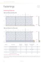
Technical data sheet | Balcony Railings Fastening Distances Balcony Railing Top Mounted a a Balcony Railing Front Mounted a a Minimum distance Maximum distance Recommended distance Distance borehole to edge Horizontal borehole distance Vertical borehole distance (1) Vertical borehole distance (2) Frame without perforation Panels longer than 2.5m shall at least have joints of 6mm. The values given are guidelines and do not release you from having an object-related inspection carried out by a qualified engineer. Test results for the tests according to ETB Guideline, EN 789, EN1048, EN 14358, EN...
Open the catalog to page 6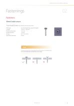
Technical data sheet | Balcony Railings Fasteners Metal Substructure Truss-head Screw Material: Length: Nominal diameter: Head diameter: Drives: Borehole diameter: (self-drilling with sealing washer) Bi-metal (Stainless steel A2/Steel) 26 mm / 38 mm 5.5 mm 14 mm SIT® 25, TX 25 8 mm Note Screws and rivets are to be placed concentrically in the drilled holes. NO COUNTERSUNK SCREWS MUST BE USED!
Open the catalog to page 7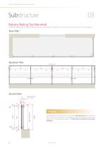
Technical data sheet | Balcony Railings Balcony Railing Top Mounted The following illustrations with their dimensions are only examples of a possible construction and serve for a better understanding. Floor Plan Panel joint Section Plan The details of the railing statics, including the dimensioning of the substructure, must be carried out in accordance with the structural and static regulations of the respective region and defined by the metal construction company.
Open the catalog to page 8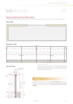
Technical data sheet | Balcony Railings Balcony Railing Front Mounted The following illustrations with their dimensions are only examples of a possible construction and serve for a better understanding. Floor Plan Panel joint Section Plan Angle profile Overhang the panel a maximum of 100 mm below the last fixing point. Otherwise there is a risk that the panels will bend slightly below the last fixing point and there will be an overtooth between the individual panels. The details of the railing statics, including the dimensioning of the substructure, must be carried out in accordance with the...
Open the catalog to page 9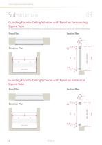
Technical data sheet | Balcony Railings Guarding Floor-to-Ceiling Window with Panel on Surrounding Square Tube The following illustrations with their dimensions are only examples of a possible construction and serve for a better understanding. Floor Plan Elevation Plan Guarding Floor-to-Ceiling Window with Panel on Horizontal Square Tube Floor Plan Elevation Plan
Open the catalog to page 10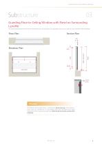
Technical data sheet | Balcony Railings Guarding Floor-to-Ceiling Window with Panel on Surrounding L-profile The following illustrations with their dimensions are only examples of a possible construction and serve for a better understanding. Floor Plan Elevation Plan Hinweis The details of the railing statics, including the dimensioning of the substructure, must be carried out in accordance with the structural and static regulations of the respective region and defined by the metal construction company.
Open the catalog to page 11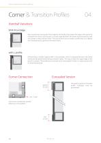
Technical data sheet | Balcony Railings Corner & Transition Profiles Handrail Variations With Front Edge We recommend covering the front edge for the handrail to protect the edge of the panel for example from hail or driving rain, to avoid a gap between the frame and the panel as well as to create a clean uniform finish. This can be done with a simple L-profile that runs slightly over the panel and is glued on the metal frame. with L-profile Alternatively, a smaller angle profile is also possible, which is clamped between the metal frame and the panel before being screwed in place. This way,...
Open the catalog to page 12All Bruag Design Factory AG catalogs and technical brochures
 Innovative Cladding Elements
25 Pages
 Ventilated Façade Solutions
9 Pages
 Noise-Virus-Catcher®
1 Page
 Zeitgeist 2016
2 Pages


Archived catalogs
 Acoustics Elements
3 Pages
 CELLON® design
8 Pages
 Zeitgeist 2015
4 Pages
 Brève Information CELLON®
2 Pages


- Bruag decorative panel
- Bruag cladding
- Industrial planter
- Exterior planter
- Industrial wallcovering
- Contemporary flower box
- Interior wall-covering
- Bruag interior decorative panel
- Commercial planter
- Bruag wall-mounted decorative panel
- Commercial decorative panel
- Bruag acoustic panel
- Bruag panel cladding
- Fencing
- Public space planter
- Commercial wall-covering
- Cover decorative panel
- Bruag commercial acoustic panel
- Industrial suspended ceiling