- Catalogs
- Bruag Design Factory AG
- A.1 Technical Sheet Ventilated Façade
- Company
- Products
- Catalogs
- News & Trends
- Exhibitions
A.1 Technical Sheet Ventilated Façade
1 /19Pages

A.1 Technical Sheet Ventilated Façade
1 /19Pages
Catalog excerpts
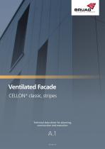
Ventilated Facade CELLON® classic, stripes Technical data sheet for planning, construction and execution
Open the catalog to page 1
Technical data sheet | Ventilated Facade Table of Contents General Information Material Panel Formats Data Transmission for Orders Storage and Cleaning Instructions Cutting and Drilling Guidelines Fastenings Fastening Distances Fasteners Concealed Mounting with Gluing Systems Substructure Wooden Substructure Metal Substructure Corner & Transition Profiles Corner Constructions Corner Profiles Construction Solutions Facade Constructions Window Details Base Details Flat Roof Connections Pitched Roof Connections
Open the catalog to page 2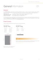
Technical data sheet | Ventilated Facade General Information Material Our CELLON® panel is a high-pressure laminate panel (HPL Compact or solid core panel) consisting of 70% cellulose webs and 30% phenolic resin. The extremely weather and frost-resistant material is ideal for outdoor applications. Application area: Panel thickness (weight): Reaction to fire class: mounted vertically in outdoor areas (e.g. facades, balcony railings) 8mm (approx. 12kg/m²), 10mm (approx. 15kg/m²) RF2, B1 (DIN 4102-1), B-s1-d0 (EN 13501-1) The raw panels are project-specifically cut to the desired dimensions using...
Open the catalog to page 3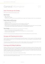
Technical data sheet | Ventilated Facade General Information Data Transmission for Orders Please note the following when placing an order: Data Format DWG / DXF Data Cadwork 2D or 3D Data Parts lists in Excel (if only as Excel without CAD file is sent, it might result in additional work in our work preparation) Data Content and Structure Panels are drawn on a separate layer Drawing in 1:1 ratio Measurement of at least one long and short side to be able to verify the scale Boreholes (drawn as a closed circle), cut-outs, etc. are marked accordingly Special requests for grouping and/or palletisation...
Open the catalog to page 4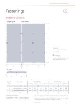
Technical data sheet | Ventilated Facade Fastening Distances Single-span borehole Ø 8 mm can be drawn directly in DXF/DWG file fixed point Fixed point 5.5 mm can be drawn directly in the DXF/DWG (only necessary for metal substructure). a Maximum distance according to wind load qek (wind pressure or suction) Distance borehole to edge Horizontal borehole distance Vertical borehole distance Reciprocal conversion: c (adjusted) = b (max) / b (effectiv) x c (max) b (adjusted) = c (max) / c (effectiv) x b (max) The values given are guidelines and do not release you from having an object-related inspection...
Open the catalog to page 5
Technical data sheet | Ventilated Facade Fasteners Wooden Substrucure Truss-head Screw Stainless steel A2 38 mm 4.8 mm 12 mm TX20 8 mm Material: Length: Nominal diameter: Head diameter: Drives: Borehole diameter: Metal Substructure Truss-head Screw Material: Length: Nominal diameter: Head diameter: Drives: Borehole diameter: (self-drilling with sealing washer) Bi-metal (Stainless steel A2/Steel) 26 mm / 38 mm 5.5 mm 14 mm SIT® 25, TX 25 8 mm Blind Rivet Material: Length: Nominal diameter: Head diameter: Drives: Borehole diameter: Aluminium/Stainless steel A2 8-13 mm 5.0 mm 14 mm Blind rivet tool...
Open the catalog to page 6
Technical data sheet | Ventilated Facade Concealed Mounting with Gluing Systems An alternative to mechanical attachment with screws or rivets is to glue the CELLON® panel with a suitable adhesive system. The adhesive system must be permanently flexible and come from a qualified adhesive system manufacturer approved for the mounting of Facade panels. Depending on the approval of the adhesive system manufacturer, CELLON® panels can be used on both wooden and metal substructures. The local regulations and test standards for adhesive installation, project-related approval by the adhesive system manufacturer...
Open the catalog to page 7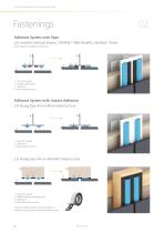
Technical data sheet | Ventilated Facade Adhesive System with Tape z.B. Innotect Adhesal Project, DOWSIL™ 896 PanelFix, SikaTack® Panel (test reports available separately) CELLON® panel Double-sided tape Adhesive Metal substructure Adhesive System with Instant Adhesion z.B. Bruag Easy-Fix on Metal Substructure 1 CELLON® panel 2 Adhesive 3 Metal substructure z.B. Bruag Easy-Fix on Wooden Substructure 4 CELLON® panel EPDM rubber backing strips* Adhesive Wooden substructure * Special EPDM rubber backing strips for adhesive mounting on wooden substructure
Open the catalog to page 8
Technical data sheet | Ventilated Facade The substructure can be made of wood or metal. Material and load-bearing capacity must comply with the applicable standards. Compliance with the static and construction guidelines is the responsibility of the processor. Wooden Substructure Batten Width in Joint Area Batten Thickness with Open Horizontal Joints with Closed Horizontal Joints L-Profil Horizontal joints can be left open. In this case, the ventilation space must be at least 40 mm. (cf. chapter 1.16.1 Techinfo 4 of the SFHF). Horizontal joints can be closed with L or Z profiles, for example....
Open the catalog to page 9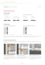
Technical data sheet | Ventilated Facade Metal Substructure Profile Width in Joint Area Profile Depth with Open Horizontal Joints with Closed Horizontal Joints L-Profil Horizontal joints can be left open. In this case, the ventilation space must be at least 40 mm. (cf. chapter 1.16.1 Techinfo 4 of the SFHF). Horizontal joints can be closed with L or Z profiles, for example. Common aluminum or plastic profiles can be used. Construction Specifications In order to cope with the greater linear expansion of a metal substructure, the following design measures must be observed: fixed points floating...
Open the catalog to page 10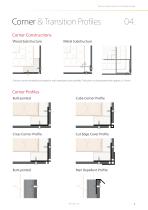
Technical data sheet | Ventilated Facade Corner & Transition Profiles Corner Constructions Wood Substructure Metal Substructure Corners can be formed butt-jointed or with standard corner profiles. The joint is to be planned with approx. 6 - 8 mm. Corner Profiles Butt-jointed Cube Corner Profile Cross Corner Profile Cut Edge Cover Profile Rain Repellent Profile
Open the catalog to page 11
Technical data sheet | Ventilated Facade Construction Solutions Facade Constructions Aluminum Console with Wooden Substructure Wall Aluminum bracket (without thermal bridges) Insulation Aluminium angle Wind barrier Batten EPDM rubber backing strips CELLON® panel Aluminium Console with Metal Substructure Wall Aluminum bracket (without thermal bridges) Insulation Aluminium angle Wind barrier Metal profile (e.g. Omega-, Z-, square profile) CELLON® panel
Open the catalog to page 12All Bruag Design Factory AG catalogs and technical brochures
 Innovative Cladding Elements
25 Pages
 Ventilated Façade Solutions
9 Pages
 Noise-Virus-Catcher®
1 Page
 Zeitgeist 2016
2 Pages


Archived catalogs
 Acoustics Elements
3 Pages
 CELLON® design
8 Pages
 Zeitgeist 2015
4 Pages
 Brève Information CELLON®
2 Pages


- Bruag decorative panel
- Bruag cladding
- Industrial planter
- Exterior planter
- Industrial wallcovering
- Bruag interior decorative panel
- Modern planter
- Interior wall-covering
- Commercial decorative panel
- Bruag wall-mounted decorative panel
- Commercial planter
- Bruag panel cladding
- Bruag acoustic panel
- Cover decorative panel
- Public space planter
- Commercial wall-covering
- Fencing
- Industrial suspended ceiling
- Bruag commercial acoustic panel