
- Catalogs
- Breeze Controls
- Breeze V7-05 Datasheet

Breeze V7-05 Datasheet
Breeze V7-05 Datasheet
Description:
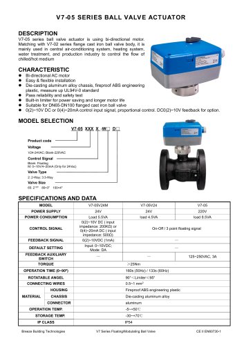
The V7-05 series ball valve actuator is designed with a bi-directional motor and is compatible with the V7-02 series flange cast iron ball valve body. It is primarily used in central air-conditioning systems, heating systems, water treatment, and production industries to control the flow of chilled or hot mediums.
Characteristics:
- Bi-directional AC motor
- Easy and flexible installation
- Constructed with a die-casting aluminum alloy chassis and fireproof ABS engineering plastic, meeting UL94V-0 standards
- Reliability and safety tested
- Built-in limiter for power saving and extended motor life
- Suitable for DN65-DN100 flanged cast iron ball valves
- Control input signals: 0(2)~10V DC or 0(4)~20mA, with proportional control and optional DC0(2)~10V feedback
Specifications and Data:
Models include V7-05V24M, V7-05V24, and V7-05, with power supplies of 24V or 220V. Power consumption varies by model, with control signals including 0(2)~10V DC or 0(4)~20mA DC, and feedback signals available for certain models. The torque is ≥25Nm, with an operation time of 160s (50Hz) or 133s (60Hz) for a 0~90º rotation. The housing is made of fireproof ABS engineering plastic, and the chassis is die-casting aluminum alloy. The operational temperature range is -5~+50℃, with a storage temperature range of -30~+70℃. The IP class is IP54.
Manual Operation and Installation:
Instructions for manual operation and installation are provided, emphasizing the importance of cutting off the power supply during maintenance and ensuring proper installation of the actuator cover during operation.
Wiring:
Details are provided for On-Off/Floating Control, On-Off/Floating Control with feedback, and Modulating Control.
Warning:
- Always cut off the power supply when repairing or maintaining.
- Do not connect or disconnect wires when the power is on.
- Ensure the actuator cover is properly installed when the actuator is operational.
PCB Setting:
Calibration and operation modes are described, including the process for switching between modes using the JP1 switch and SW1 calibration/reset button. The calibration mode involves setting the JP1 switch to "ON," pressing the SW1 button, and observing the power LED flashing during calibration. After calibration, the JP1 switch should be set to "OFF" to return to operation mode.
Catalog excerpts
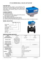
V7-05 series ball valve actuator is using bi-directional motor. Matching with V7-02 series flange cast iron ball valve body, it is mainly used in central air-conditioning system, heating system, water treatment, and production industry to control the flow of chilled/hot medium Bi-directional AC motor Easy & flexible installation Die-casting aluminum alloy chassis, fireproof ABS engineering plastic, measure up UL94V-0 standard Pass reliability and safety test Built-in limiter for power saving and longer motor life Suitable for DN65-DN100 flanged cast iron ball valve 0(2)~10V DC or 0(4)~20mA control input signal, proportional control. DC0(2)~10V feedback for option. Product code - Control Signal - Blank: Floating Valve Type - Valve Size - Breeze Building Technologies V7 Series Floating/Modulating Ball Valve
Open the catalog to page 1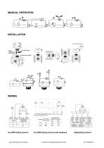
MANUAL OPERATION (C) (N.O) (C) (N.O)(GREEN) (BLUE) (YELLOW) (RED) (BLUE) (BLUE) (BLACKHBLACK) 1 (RED) 2(BLUE) 3{+YELLOW) 4{+GREEN) POWER SUPPLY CONTROL SIGNAL FEEDBACK SUPPLY SIGNAL 0(2}~10VDC SIGNAL On-Off/Floating Control On-Off/Floating Control with feedback Modulating Control Breeze Building Technologies V7 Series Floating/Modulating Ball Valve
Open the catalog to page 2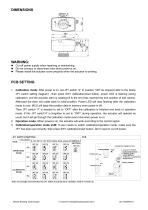
• Cut off power supply when repairing or maintaining. • Do not connect or disconnect wire when power is on. • Please install the actuator cover properly when the actuator is working. 1. Calibration mode: After power is on, set JP1 switch “4” to position “ON” as request (refer to the below JP1 switch setting diagram) , then press SW1 calibration/reset button, power LED is flashing during calibration, and the actuator stem is rotating till to the end (has reached the end position of ball valves). Afterward the stem will rotate back to initial position. Power LED will stop flashing after the calibration...
Open the catalog to page 3All Breeze Controls catalogs and technical brochures
 Breeze TV01 Datasheet
18 Pages
 Breeze V7-06 Datasheet
2 Pages
 Breeze V7-04 Datasheet
2 Pages
 Breeze V7-03 Datasheet
2 Pages
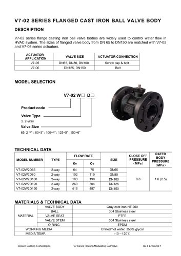 Breeze V7-02 Datasheet
2 Pages
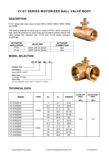 Breeze V7-01 Datasheet
2 Pages
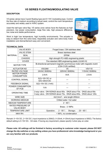 Breeze V5 Datasheet
3 Pages
 Breeze V4 Datasheet
8 Pages
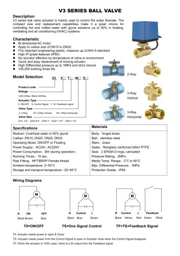 Breeze V3 Datasheet
2 Pages
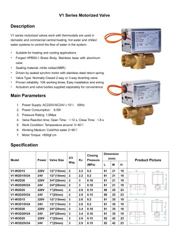 Breeze v1 datasheet
2 Pages
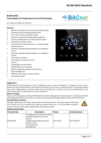 Breeze BC106-4AED Datasheet
15 Pages
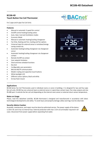 Breeze BC106-4D Datasheet
18 Pages
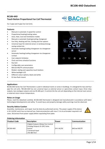 Breeze BC106-4AD Datasheet
14 Pages
 Breeze BC107-2A/4A LoRaWAN
3 Pages
 Breeze BC107-2/4 LoRaWAN
2 Pages
 Breeze BC205Z-T Datasheet
3 Pages
 Breeze BC105W-4D Datasheet
3 Pages
 Breeze BC105-AC&HP Datasheet
2 Pages
 Breeze BC103-AC&HP Datasheet
2 Pages
 Breeze BC507 Datasheet
2 Pages
 Breeze BC107W-4E Datasheet
3 Pages
 Breeze BC105W-2/4D Datasheet
3 Pages
 Breeze BC104W-4D Datasheet
6 Pages
 Breeze BC105W-4ED Datasheet
3 Pages
 Breeze BC204-E Datasheet
6 Pages
 Breeze BC203-E Datasheet
2 Pages
 Breeze BC205-E Datasheet
3 Pages
 Breeze BC207-E Datasheet
2 Pages
 Breeze BC204 Datasheet
2 Pages
 Breeze BC205W Datasheet
3 Pages
 Breeze BC205Z-T Datasheet
3 Pages
 Breeze BC205W-T Datasheet
3 Pages
 Breeze BC207W-T Datasheet
3 Pages
 Breeze BC203 Datasheet
2 Pages
 Breeze BC104-4AM Datasheet
2 Pages
 Breeze BC107-4EDM Datasheet
3 Pages
 Breeze BC107-2A/4A Datasheet
3 Pages
 Breeze BC105-4EDM Datasheet
2 Pages
 Breeze BC105-4AEDM Datasheet
2 Pages
 Breeze BC105-4AD Datasheet
2 Pages
 Breeze BC103-4ADM Datasheet
2 Pages
 Breeze BC103-2AEDM Datasheet
2 Pages
 Breeze BC103-4EDM Datasheet
2 Pages
 Breeze BC35-4 Datasheet
2 Pages
 Breeze BC104-4M Datasheet
2 Pages
 Breeze BC104W-4 Datasheet
2 Pages
 Breeze BC105W-4 Datasheet
2 Pages
 Breeze BC105-4DM Datasheet
2 Pages
 Breeze BC103S-ACDM Datasheet
2 Pages
 Breeze BC107-2/4 Datasheet
3 Pages
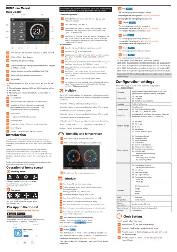 Breeze BC107-4DM Datasheet
3 Pages
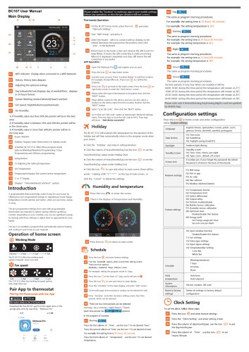 Breeze BC107W-2/4 Datasheet
3 Pages
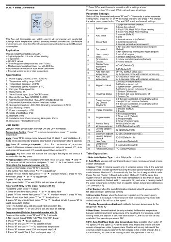 Breeze BC103-4DM Datasheet
2 Pages
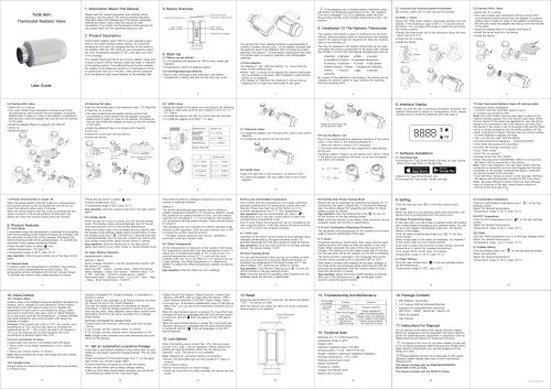
- Industrial thermostat
- White thermostat
- Programmable thermostat
- Heating thermostat
- Digital thermostat
- Wall-mounted thermostat
- Thermostat with digital display
- Room thermostat
- Wireless thermostat
- Thermostat with touchscreen
- Black thermostat
- Air conditioning thermostat
- Manual thermostat
- Recessed thermostat
- WiFi thermostat
- Underfloor heating thermostat
- Home automation system thermostat
- Manual thermostatic valve
- Thermostatic valve
- Recessed wall thermostat