- Catalogs
- Breeze Controls
- Breeze BC106-4AD Datasheet
Breeze BC106-4AD Datasheet
1 /14Pages

Breeze BC106-4AD Datasheet
1 /14Pages
Catalog excerpts
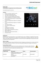
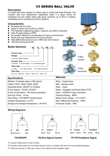
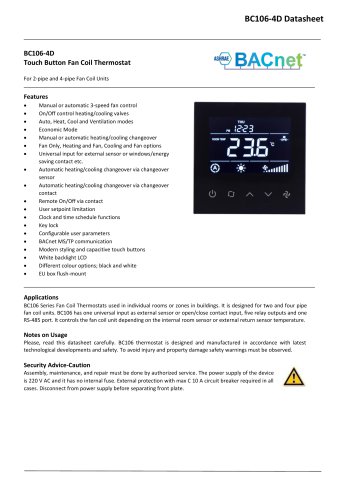
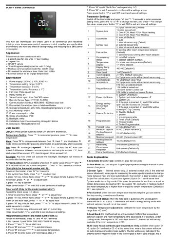
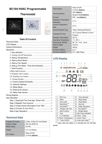
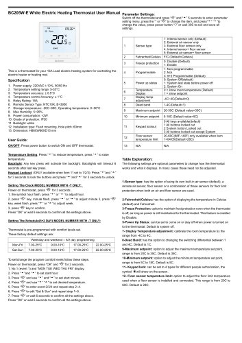
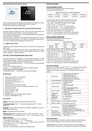
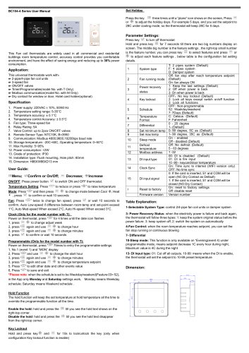
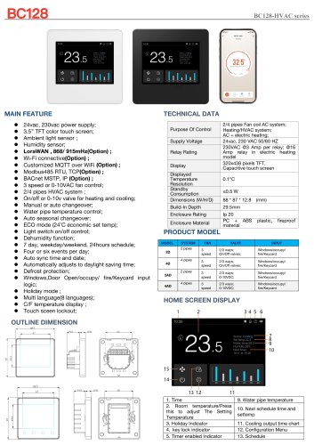
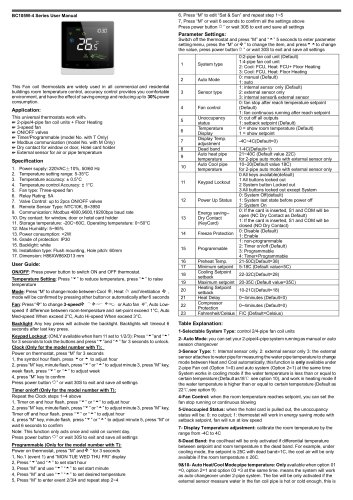
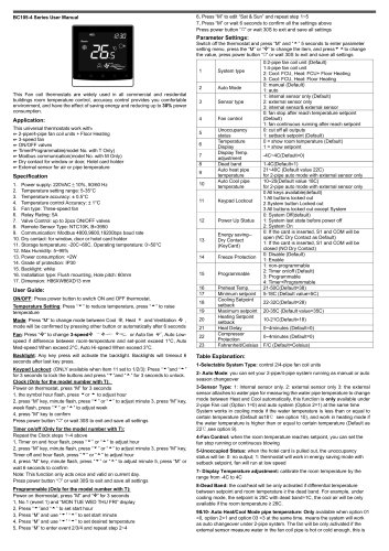
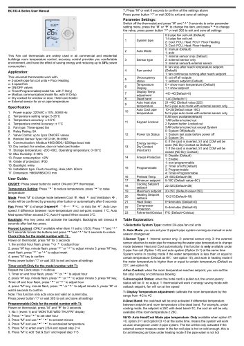
BC106-4ADTouch Button Proportional Fan Coil Thermostat For 2-pipe and 4-pipe Fan Coil Units • Manual or automatic 3-speed fan control • Proportional heating/cooling valves • Auto, Heat, Cool and Ventilation modes • Manual or automatic heating/cooling changeover • Fan Only, Heating and Fan, Cooling and Fan options • Universal input for external sensor or windows/energy saving contact Ttc. • Automatic heating/cooling changeover via changeover sensor • Automatic heating/cooling changeover via changeover contact • User setpoint limitation • Clock and time schedule functions • Configurable user parameters • BACnet MS/TP communication • Modern styling and capacitive touch buttons • Different colour options; black and white BC106-4AD Series Fan Coil Thermostats is used in individual rooms or zones in buildings. It is designed for two and four pipe fan coil units. TBC106-4AD has one universal input as external sensor or open/close contact input, three relay outputs, two analogue outputs and one RS-485 port. It controls the fan coil unit depending on the internal room sensor or external return sensor temperature. Please, read this datasheet carefully. BC106-4AD thermostat is designed and manufactured in accordance with latest technological developments and safety. To avoid injury and property damage safety warnings must be observed. Security Advice-Caution Assembly, maintenance, and repair must be done by authorized service. The power supply of the device is 24 V AC/DC and it has no internal fuse. External protection with max C 5 A circuit breaker required in all cases. Disconnect from power supply before separating front plate.
Open the catalog to page 1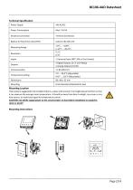
Power Supply Mounting Location Thermostat is suggested to be installed indoors, a place with around 1.5m height above the floor so that it can measure the average room temperature. It should be away from direct sunlight, any cover or any heat source, to avoid false signal for temperature control. CAUTION: Cut off the supply power at the circuit breaker or fuse before installation to avoid fire,
Open the catalog to page 2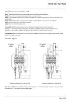
Please follow below instructions during mounting. Step 1: Take the thermostat out from the package. Get the datasheet inside the package. Step 2: Connect the wires properly according to the wiring diagram below. Step 3: Separate the front plate and the back plate, and then use screwdriver to fix the back plate into the electric box with 4 screws. Step 4: Attach the front plate to the back plate, making sure the pin plates on each side are well matched. Step 5: Compare it with the pictures after installation. Step 6: Power on the thermostat to work. Important Note 1: It is recommended to use the...
Open the catalog to page 3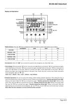
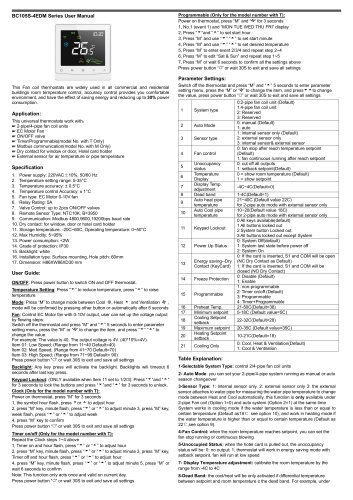
<$> $ 1 ❖ STmlll Cooling Valve Heating Valve Underfloor Heating Valve On/Off Mode Fan Speed Increase/ Decrease/ Key Key Key Up Down • Mode Selection: Press the “M" key to change the mode of the device. Active mode options are as follows. • Fan Selection: When the "»$* " key is pressed, fan speed can be changed as Low, Med, High, Auto. • Time Settings: After pressing the “M" key for 3 seconds, year digits flashes on the panel. “M" key is pressing once again, month digit flashes on the panel. “M" key is pressed once again, day digit flashes on the panel. “M" key is pressed once again, hour digit...
Open the catalog to page 4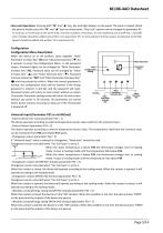
• Key Lock Operations: Pressing both “M” and “” key, key lock digit displays on the panel. The panel is locked. When the panel is locked, press the “M” and “” keys to unlock panel. “Key Lock” options can be changed via parameter P6. To lock two or more keys at the same time; sum the numbers of the keys. To lock mode key and on/off key, 1 (on/off) and 2 (mode) should be added and written 3 to parameter P6. To lock setpoint and fan speed, 4 (setpoint) and 8 (fan speed) should be added and written 12 to parameter P6 Configuration Configuration Menu Description When the device on or off position,...
Open the catalog to page 5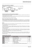
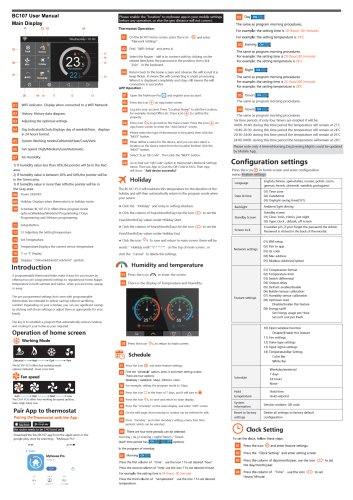
The output diagram of the valve according to the relation between Ts and Tr is given below. Valve Output Heating Mode iyHysteresisj yHysteresisj Cooling Mode : Room Temperature ; Setpoint Fan/Valve Control Selection (Parameter P41 or via BACnet) In vRalOveOinMdepeCnOdeNntTmRodOe,Lt hPe AfaNn oEpLerates according to manual fan selection or automatic fan control. When valve is closed, the fan will continue to operate. In valve dependent mode, the fan will be closed when the valve is closed. If the valve is open, the fan will operate according to manual fan selection or automatic fan control. The...
Open the catalog to page 6
BACnet Parameters According to BACnet standards, MSTP port configurations are as follows; -8 Data Bits, None Parity, 1 Stop Bit Baudrate : 9600, 19200, 38400, 76800. Default 76800 Note 1: The MAC address can be changed via configuration menu.
Open the catalog to page 8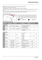
Note 2: Device Instance Number (Device ID) is automatically calculated as below. For example: Mac: 13, Loop ID: 1 => Device ID = 856 * 1000 + 1 * 200+ 13 = 856213 When the MAC address is changed via configuration menu, the Device ID is automatically recalculated to avoid network ID conflict. As a property of Device Object, Device ID value is writable via BACnet between 0 and 4194302. Once the Device ID is changed via BACnet, Device ID automatic calculation mentioned above is ineffective. When the thermostat front plate is flipped, the EOL resistor DIP switch is seen on the upper right side of...
Open the catalog to page 9All Breeze Controls catalogs and technical brochures
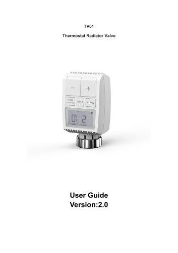 Breeze TV01 Datasheet
18 Pages
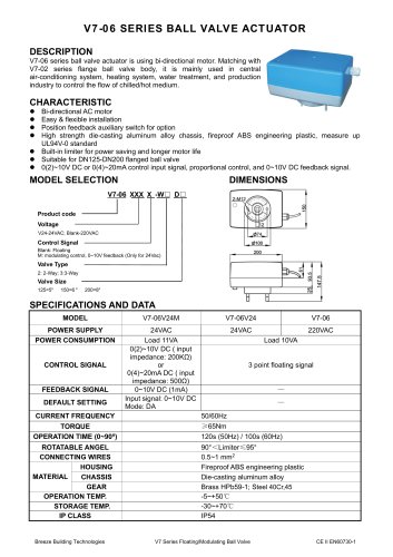 Breeze V7-06 Datasheet
2 Pages
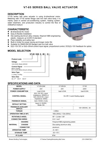 Breeze V7-05 Datasheet
3 Pages
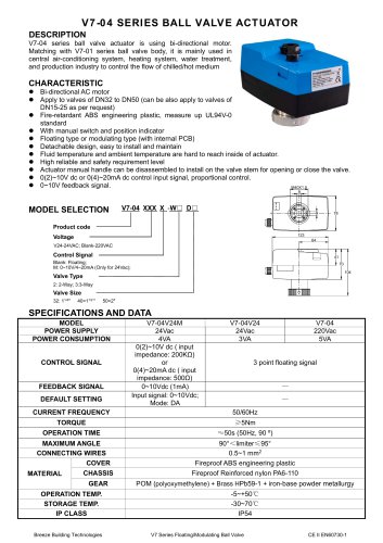 Breeze V7-04 Datasheet
2 Pages
 Breeze V7-03 Datasheet
2 Pages
 Breeze V7-02 Datasheet
2 Pages
 Breeze V7-01 Datasheet
2 Pages
 Breeze V5 Datasheet
3 Pages
 Breeze V4 Datasheet
8 Pages
 Breeze V3 Datasheet
2 Pages
 Breeze v1 datasheet
2 Pages
 Breeze BC106-4AED Datasheet
15 Pages
 Breeze BC106-4D Datasheet
18 Pages
 Breeze BC107-2A/4A LoRaWAN
3 Pages
 Breeze BC107-2/4 LoRaWAN
2 Pages
 Breeze BC205Z-T Datasheet
3 Pages
 Breeze BC105W-4D Datasheet
3 Pages
 Breeze BC105-AC&HP Datasheet
2 Pages
 Breeze BC103-AC&HP Datasheet
2 Pages
 Breeze BC507 Datasheet
2 Pages
 Breeze BC107W-4E Datasheet
3 Pages
 Breeze BC105W-2/4D Datasheet
3 Pages
 Breeze BC104W-4D Datasheet
6 Pages
 Breeze BC105W-4ED Datasheet
3 Pages
 Breeze BC204-E Datasheet
6 Pages
 Breeze BC203-E Datasheet
2 Pages
 Breeze BC205-E Datasheet
3 Pages
 Breeze BC207-E Datasheet
2 Pages
 Breeze BC204 Datasheet
2 Pages
 Breeze BC205W Datasheet
3 Pages
 Breeze BC205Z-T Datasheet
3 Pages
 Breeze BC205W-T Datasheet
3 Pages
 Breeze BC207W-T Datasheet
3 Pages
 Breeze BC203 Datasheet
2 Pages
 Breeze BC104-4AM Datasheet
2 Pages
 Breeze BC107-4EDM Datasheet
3 Pages
 Breeze BC107-2A/4A Datasheet
3 Pages
 Breeze BC105-4EDM Datasheet
2 Pages
 Breeze BC105-4AEDM Datasheet
2 Pages
 Breeze BC105-4AD Datasheet
2 Pages
 Breeze BC103-4ADM Datasheet
2 Pages
 Breeze BC103-2AEDM Datasheet
2 Pages
 Breeze BC103-4EDM Datasheet
2 Pages
 Breeze BC35-4 Datasheet
2 Pages
 Breeze BC104-4M Datasheet
2 Pages
 Breeze BC104W-4 Datasheet
2 Pages
 Breeze BC105W-4 Datasheet
2 Pages
 Breeze BC105-4DM Datasheet
2 Pages
 Breeze BC103S-ACDM Datasheet
2 Pages
 Breeze BC107-2/4 Datasheet
3 Pages
 Breeze BC107-4DM Datasheet
3 Pages
 Breeze BC107W-2/4 Datasheet
3 Pages
 Breeze BC103-4DM Datasheet
2 Pages


- White thermostat
- Programmable thermostat
- Heating thermostat
- Digital thermostat
- Wall-mounted thermostat
- Thermostat with digital display
- Room thermostat
- Wireless thermostat
- Air conditioning thermostat
- Black thermostat
- Thermostat with touchscreen
- Manual thermostat
- Recessed thermostat
- Underfloor heating thermostat
- WiFi thermostat
- Home automation system thermostat
- Radio thermostat
- Recessed wall thermostat
- Ventilation system thermostat