Catalog excerpts

BODET Time&Sport 1 rue du Général de Gaulle 49340 Trémentines I France When receiving goods please check nothing is broken otherwise make a claim near shipping company.
Open the catalog to page 1
Electrical and mechanical safety standards - Installation and maintenance of this equipment should only be carried out by qualified personnel. - Since 8000 scoreboards are connected to a mains supply, they must be installed in compliance with standard IEC 364. - Indoor use (protected against blows from balls – Standard DIN18032.3). - The mains supply for the scoreboards must include a neutral phase circuit breaker, rapidly accessible upstream from the supply. This circuit breaker must be switched off during maintenance operations. - This material must be installed before being connected to...
Open the catalog to page 2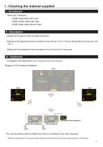
I - Checking the material supplied I - Scoreboard - There are 3 versions: > 8006 single sided with mast > 8006 double sided with mast > 8006 single sided without mast II - Description - Display of the game clock (minutes-seconds). - Display of the possession time countdown from 24 sec to 0 in 1/10 sec during the last 5 sec (ex: 4.9, 4.8...). - Display of the possession time countdown from 24 sec to 0 in seconds. III - Keyboards - Possession time keyboard: Power supplied through main keyboard. Diagram of HF wireless installation: 8025 Possession time keyboard Secondary keyboard Main keyboard...
Open the catalog to page 3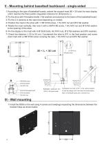
II - Mounting behind basetball backboard - single-sided 1/ According to the type of basketball boards, extend the support mast (60 × 30 tube) for each display until it reaches the final position (regulation distance for dimensions L). 2/ Fix the shoe with 4 threaded shafts + flat washers and plywood to the beam of the basketball board. 3/ Fix the 2 U sections to the mast (level depending on model). 4/ Position the mast in the shoe with 1 HM10×90 screw, 1 HU M10 nut and Ø10 flat washer. 5/ Rotate the mast vertically, then lock it with a HM10×90 screw, 1 HU M10 nut and Ø10 flat washer to the...
Open the catalog to page 4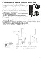
IV - Mounting behind basetball backboard - double sided 1/ Upon reception assemble the double sided 8006 shot clock on the pole. Slide the pole inside the casing and fasten it to the casing on both flat angle bracket (1 on the top and 1 at the bottom of the casing): 2/ According to the type of basketball boards, extend the support mast (60 × 30 tube) for each display until it reaches the final position (regulation distance for dimensions L). 2/ Fix the shoe with 4 threaded shafts + flat washers and plywood to the beam of the basketball board. 3/ Fix the 2 U sections to the mast (level...
Open the catalog to page 5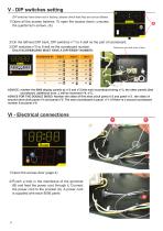
V - DIP switches setting DIP switches have been set in factory; please check that they are set as follows. 1/ Open all the access hatches. To open the access doors, unscrew the quarter-turn screws. (A). 2/ On the leftmost DIP bank, DIP switches n°1 to 4 defi ne the part of scoreboard. 3/ DIP switches n°5 to 8 defi ne the scoreboard number. EACH SCOREBOARD MUST HAVE A DIFFERENT NUMBER. Scoreboard N° Dip 5 Dip 6 Dip 7 3 off |y off |y on t0 ADVICE: number the 8006 display panels as n°2 and n°3 (the main scoreboard being n°1). the other panels (2nd scoreboard, additional...
Open the catalog to page 6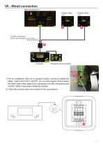
VII - Wired connection Main scoreboard n°1 Display 24sec n°2 To other scoreboards (other main scoreboard, horn case...) Possession time keyboard 1/ For an installation with one or several boards, connect a telephone cable 1 pair 0.9 mm RT+ and RT- (C) on every board. And connect the other side of the cable to the connection box (B). Disconnect the modem cable if necessary. Respect polarity. 2/ Close the access doors and switch on the scoreboard.
Open the catalog to page 7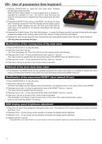
VIII - Use of possession time keyboard 1/ Pressing START/STOP (1) starts the shot clock timer. Pressing 4 this key again stops the timer. 3 5 When the timer value reaches 0, a sound signal (horn or buzzer) is 6 7 activated for a duration of 3 sec. The LED du Time Pad turns red 1 2 8 when the shot clock timer is stopped and shines green when the timer is timing. 2/ ressing the RESET Poss (2) key or the RESET 14s (8) key for more P than X seconds causes the Time Pad display and the display panels to go blank. When releasing the key, the Shot clock timer take its reset value of 24 seconds or...
Open the catalog to page 8All Bodet Sport catalogs and technical brochures
-
8000 Sports Scoreboards
24 Pages

