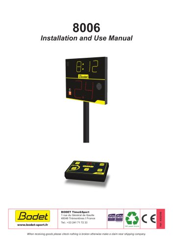
Catalog excerpts
Installation manual Ensure on delivery that the product has not been damaged during transport.
Open the catalog to page 1
2. ELECTRICAL AND MECHANICAL SAFETY STANDARDS 3 4.1 Attachment to wall bracket (Ref.: standard scoreboard reference) 4 4.2 BT6000 wall rail mount (ref: 916,427) 5 6. INDIVIDUAL FOUL PANEL INSTALLATION 12 6.1 Opening an F6 individual foul panel 12
Open the catalog to page 2
1. INTRODUCTION We would like to thank you for choosing a BODET scoreboard. This product has been carefully designed to meet your needs in accordance with ISO 9001 quality standards. We recommend reading this notice carefully before beginning installation. Retain this manual throughout the lifespan of your product so that you can refer to it when necessary. Non-contractual data. Bodet reserves the right to make certain functional, technical, design and colour changes to its devices without prior notice. Failure to follow these instructions may cause irreversible damage and invalidate the...
Open the catalog to page 3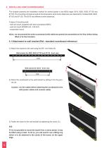
4. INSTALLING 8000 SCOREBOARDS This chapter presents the installation method for central boards in the 8000 range: 8015, 8020, 8025, 8T120 and 8T125. The mounting principle as well as the dimensions (and centre distances) are identical for models 8020, 8025, 8T120 and 8T125. The 8015 has different centre distances. 3 types of mounting exist: - wall rail mount (supplied with each scoreboard 8000) - wail rail mount BT6000 (ref.: 916 427) - suspended mount Adice: e recommend the entire scoreboard (with addionnal panels) be assembled on the floor before being w lifted in its final location. 4.1...
Open the catalog to page 4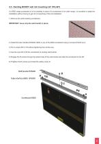
4.2 - Existing BODET wall rail mounting (ref: 916,427) If a 8000 range scoreboard is to be installed in place of a scoreboard of an older range, it is possible to adapt the installation without having to get rid of everything of the old installation. 1) Remove the entire existing scoreboard. IMPORTANT: leave only the wall bracket in place: 2) nstall the tube interface BT6000- 8000 on top of the 8000 scoreboard using 2 screws M10x30 an A. I 3) Put 2 screws M10 in B without tightening then all the way. 4) Use the eye bolt to lift the scoreboard to existing wall bracket. 5) ngage the B screws...
Open the catalog to page 5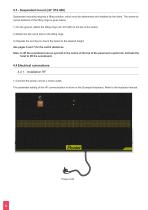
4.3 - Suspended mount (ref: 916,426) Suspended mounting requires a lifting solution, which must be determined and installed by the client. The centre-tocentre distance of the lifting rings is given below. 1) On the ground, attach the lifting rings (ref: 916,426) to the top of the board. 2) Attach the two quick links to the lifting rings. 3) Operate the winches to mount the board to the desired height. See pages 6 and 7 for the centre distances. Note: o lift the scoreboard use an eye bolt in the centre of the top of the panel and a quick link. Activate the t hoist to lift the scoreboard. 4.4...
Open the catalog to page 6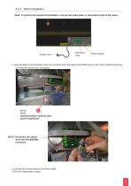
4.4.2. Wired installation Note: To perform the electrical installation, remove the metal plate on the bottom right of the panel. Power cord Electronic card Power supply 1) Connect both communication wires (A) comming from the wall socket (DIN type) on the main scoreboard panel. > Follow the colours for connection. Brown A White Communication cable to main panel (+keyboard) NOTE: iconnect the yellow D wire from the MODEM connector 2) Connect the power plug to the mains outlet. 3) Put the metal plate in place.
Open the catalog to page 7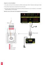
Diagram of a wired installation: 1) The cable comming from the scoreboard is AWG23, twisted paire 0.25mm². Maximum cable length: 1200m 2) The DIN wall outlet must be mounted near the scorers table. 3) he power plugs (supplied with the keyboards and 800 scoreboard) are to be connected on a 100-240VAC T outlet protected by a circuit breaker Remark: use on ly the power cord supplied with the scoreboard. Main scoreboard 1 Brown. 2 White. 3 Black (unused). 4 Red (unused). Main keyboard
Open the catalog to page 8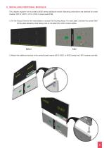
5. INSTALLING ADDITIONAL MODULES This chapter explains how to install a 8000 series additional module. Mounting instructions are identical for board models: 2NT15, 3NT15, 2T10, 2T20 or sheet metal PUB. 1) On the round remove the metal plates to access the mounting holes. For each plate, unscrew the screws then G tilt the plate delicately while taking care to not detach the LED module cables. 2) ttach the additional module in the central board inserts (8015, 8020, or 8025) using the 2 M10 screws provided: A
Open the catalog to page 9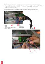
3) Wiring: Most of the wiring is carried out at the factory. This manual only covers the wiring required during installation. > wires must be connected for communication (A) and 3 wires for power (B). These wires are supplied with the 2 additional box and are to be connected using quick connectors supplied with the main scoreboard. > Follow the colours for connection. 4) Connect the ground cable to the metal plate and the chassis before putting the plate back in place. Brown A White Communication cable to main panel (+keyboard) Brown Blue Yellow/green power supply Blue Brown Yellow/ green
Open the catalog to page 10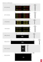
Dimensions of additional units:
Open the catalog to page 11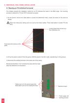
6. INDIVIDUAL FOUL PANEL INSTALLATION 6.1 Opening an F6 individual foul panel This chapter presents the installation method for an F6 individual foul panel in the 8000 range. The mounting principle is identical for F10 and FS10 individual foul panels 1) n the ground, remove the metal plates to access the attachment holes. Loosen all screws on the panel as O follows: d etach the metal panel, taking care not to pull out the ribbon cables. Three metal plates in models F10 and FS10. Loosen these three screws by a few millimetres only. Fully loosen the screws on the panel 2) Lift up the panel to...
Open the catalog to page 12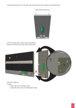
4) Using the lifting rings (ref. 916 426), raise the panel to the same height as the central board.. Lifting rings to place here 5) On the central board, detach all the metal plates.. Attach the individual foul panel to the central board: 6) Run the cables (A). 2 cables : - 1 cable with brown and white wiring - 1 cable with brown, blue and yellow/green wiring.
Open the catalog to page 13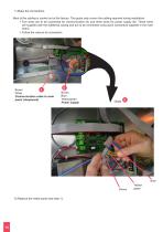
7) Make the connections. Most of the cabling is carried out at the factory. This guide only covers the cabling required during installation. > wo wires are to be connected for communication (A) and three wires for power supply (B). These wires T are supplied with the additional casing and are to be connected using quick connectors supplied in the main board. > Follow the colours for connection. Brown A White Communication cable to main panel (+keyboard) B Brown Blue Yellow/green Power supply Blue Brown 8) Replace the metal panel (see step 1). Yellow/ green
Open the catalog to page 14

