
Catalog excerpts

Guida di riferimento per protocollo MODBUS MODBUS Protocol Reference Gui
Open the catalog to page 1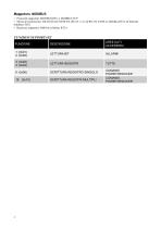
Mappatura MODBUS • Protocolli supportati: MODBUS RTU e MODBUS TCP • Mezzo di trasmissione: RS-485 HALF DUPLEX (SLOT 1 e 2) ed RS 232 (COM-2) (Modbus RTU) ed Ethernet (Modbus/TCP) • Baud rate supportati: 9600 bit/s (Mobus RTU)
Open the catalog to page 3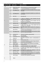
MAPPA DEIREGISTRIALLARMIEDISTATO GFCI Failure Il sensore GFCI presenta un’anomalia
Open the catalog to page 4
12 11 10 9 8 7 6 5 4 3 2 1 Modbus Write Bit = 1, inibita la write sul registro 113
Open the catalog to page 5
Potenze reattive della fase R Potenze reattive della fase S Potenze reattive della fase T Nota: In caso il valore non sia disponibile, viene trasmesso il valore OxFFFF MAPPA DEI REGISTRIIDENTIFICAZIONE Codice per esecuzione comando. Comandi supportati: 113 Cmd_code 40 (0x0028): Reset E-total and h-Total record Integer 50 (0x0032): Applicazione parametri / comandi presenti nei registri "Power Reducer” 0x0000+Cmd code Comando in elaborazione Il codice comando e errato o i parametri della tabella POWER REDUCER sono fuori range Il comando non e gestito dall’inverter 0x0F00+Cmd_code Il...
Open the catalog to page 6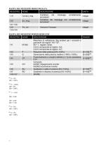
MAPPA DEI REGISTRI MODCOM DATA REGISTRO Contatore dei messaggi correttamente Integer processati Contatore dei messaggi non correttamente Integer processati Versione Firmware MAPPA DEI REGISTRI POWER REDUCER REGISTRO DESCRIZIONE Maschera di validazione (big endian) per i comandi e parametri dei registri 142÷157. Bit = 1, registro valido. Il bit 0 corrisponde al registro 142; Il bit 5 corrisponde al registro 147; Riduzione della potenza [0%÷100%] Generazione della potenza reattiva [-100%;+100%] Funzionamento a cos(phi) definito [-1;1] con precisione 0.01 Comando 0x0001=Spegnimento inverter...
Open the catalog to page 7
Descrizione generale di funzionamento dei comandi Power Reducer La programmazione dei parametri della funzionalità di power reducing segue la sequenza: 1. Il master Modbus esegue una o più operazioni di scrittura (a registro singolo o registri multipli) nei registri che vanno dal 141 al 147. Durante questa fase l’inverter non attualizza i parametri che vengono scritti. 2. Il master Modbus esegue una scrittura nel registro 113 del codice 50 (0x0032). Alla ricezione di questo comando, l’inverter rende operativi i parametri scritti...
Open the catalog to page 8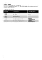
MODBUS mapping • Supported protocols: MODBUS RTU and MODBUS TCP • Hardware: RS-485 HALF DUPLEX (SLOT 1 and 2) / RS 232 (COM-2) (Modbus RTU) and Ethernet (Modbus/TCP) • Baud rate: 9600 bit/s (Mobus RTU) SUPPORTED FUNCTIONS
Open the catalog to page 9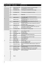
ALARMS AND STATUS REGISTERS MAP 1 GFCI Failure GFCI circuit failure
Open the catalog to page 10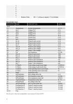
7 6 5 4 3 2 1 Modbus Write Bit = 1, writing on register 113 is inhibited Nota: In caso il valore non sia disponibile, viene trasmesso il valore OxFFFF
Open the catalog to page 11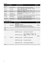
0x0000+Cmd code Command is in execution The command is wrong or the Power Reducing values are wrong. Integer 0x0200+Cmd_code Command not supported. 0x0F00+Cmd code Command executed.
Open the catalog to page 12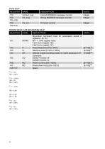
Correct_msg Err_msg Correct MODBUS messages counter Wrong MODBUS messages counter Integer Integer Firmware version POWER REDUCER REGISTERS MAP REGISTER DESCRIPTION Big-endian command mask for parameters stored in registers 142-157. Bit = 1, Valid register value. Il bit 0 is for register 142; Il bit 5 is for register 147; Power Reduction [0%÷100%] Reactive power [-100%;+100%] Defined cos(phi) working mode [-1;1] with accuracy 0.01 Command 0x0001=Inverter off 0x0002=Inverter on Power up ramp [0%÷100%] Power down ramp [0%÷100%] Spare
Open the catalog to page 13
Power reducing: general description of Modbus actions When programming the parameters of Power reducing the following sequence is required: 1. The Modbus master writes registers 141 to 147 (single write or multiple write). The inverter does not apply these register values 2. The Modbus master writes a value of 50 (0x32) in register 113 to command the inverter to apply the set of parameters. 3. The Modbus master can verify the command execution status reading the register 117. Note that the 113 register could be not...
Open the catalog to page 14
RPS SpA - Riello Power Solutions Via Somalia, 20 20032 Cormano (Ml) Italy
Open the catalog to page 16All Aros solar technologie catalogs and technical brochures
-
 Sirio Central Station
2 Pages
-
 General catalogue Photovoltaic
76 Pages
-
 HV-MT Central Inverters
6 Pages
-
 Central Inverters
13 Pages
-
 TL inverters
9 Pages
-
 SPS
SPS6 Pages
-
 REFERENCE LIST 2011
36 Pages
-
 TECHNICAL INFORMATION
6 Pages