
- Catalogs
- ARCELORMITTAL Long
- ArcelorMittal Piling Handbook

ArcelorMittal Piling Handbook

ArcelorMittal Piling Handbook
The 2008 revision of the Eighth Edition of the Piling Handbook by ArcelorMittal emphasizes the company's leadership in steel production and foundation solutions. It serves as a technical guide for design engineers, with updates in sealants, noise, vibration, and installation.
- Introduction: Steel sheet piling offers strength and durability with minimal weight, available in Z and U forms for various contract requirements.
- Typical Uses: Applications include river control, ports, bridge abutments, basements, and load-bearing foundations.
- Steel Qualities: Hot rolled steel piles comply with EN 10248 Part 1, while cold formed piles follow EN10249 Part 1 standards.
- Product Tolerances: Hot rolled products adhere to EN 10248 Part 2, with specific tolerances for dimensions.
- Section Profiles: Detailed drawings and specifications are available online, with periodic reviews.
- Maximum and Minimum Lengths: Steel sheet piles can be supplied up to 31m, with options for splicing longer lengths on-site.
- Interlocking Options: Various interlock systems are available for different pile types.
- Handling Holes: Optional handling holes can be provided for ease of use.
- Plating for Section Modulus and Durability: Plates can enhance strength and durability, especially in high corrosion areas.
- Corners and Junctions: A range of hot rolled special sections is available for creating corners and junctions.
The document provides detailed specifications and properties of various U profile piles, including dimensions, sectional mass, moments of inertia, and section moduli.
Tables list dimensions and properties of different pile sections, crucial for engineers to select the appropriate pile type.
U piles can be interlocked in pairs to reduce handling and pitching operations.
The section modulus of sheet piles is developed through factors like friction and embedment, with additional measures like crimping or welding for resistance to shear forces.
Details on crimping and welding techniques are provided, enhancing connection stability and performance.
Advises on the use of crimping or welding in specific conditions to ensure structural integrity.
Steel sheet piling can form a complete circle without corner piles, with a maximum deviation angle of 5° for single piles.
Dimensions and properties for AS-500 Straight Web piles are detailed, with interlocking capabilities.
Junction piles are assembled by welding, with specific strength values for different sheet pile types.
The HZ/AZ pile system is a combined wall system using HZ king piles and AZ sheet piles, with innovative combinations available.
Welded box piles are fabricated from conventional hot rolled sheet piles, suitable for resisting vertical and horizontal forces.
- CAU, CU, and CPU-R Box Piles: Dimensions, sectional areas, mass, moments of inertia, and elastic section moduli are provided for different configurations.
- Quadruple Box Piles: Detailed specifications for CAU and CU quadruple box piles are provided.
- CAZ + AZ Combinations: Mass, moment of inertia, and elastic section modulus data for various configurations are provided.
- Combined Walls with U-type Sections: Specifications for AU and PU box and sheet piles are detailed.
- Development of rolled corner sections for creating load-bearing foundations is described, highlighting environmental benefits and load testing capabilities.
- Tables provide dimensions and properties for foundations using sheet pile/omega combinations.
- Jagged walls are formed by threading AZ piles in reverse, creating efficient barriers for specific applications.
- Introduces cold-formed sheet piles, expanding the range of available sections.
- Specifications for PAL and PAU sections are provided, including dimensions, sectional properties, and coating details.
Preparation of the steel surface is crucial for performance. Sealants prevent water flow through interlocks in sheet piles, with different types offering varying levels of durability and performance.
Soft sealants act as displacement seals, while firmer sealants form compression seals. Hydrophilic sealants swell upon water contact.
Minimizing interlocks reduces water ingress risk. Techniques like pitch and drive are preferred for better sealant performance.
Sealants should be applied to specific interlocks based on their position and exposure.
Sealants exhibit varying durability against chemicals, with permeability depending on proper interlocking and application.
Welding is effective for sealing interlocks, especially in accessible areas.
Steel piling is susceptible to corrosion, with protective measures extending the life of steel piles.
1. Soil Corrosion: Maximum rate is 0.012 mm/side per year.
2. Atmospheric Corrosion: Rates vary by environment, with higher rates near the sea.
3. Fresh Water Corrosion: Lower rates than sea water.
4. Marine Environments: Different zones have varying rates, with minimal corrosion below bed-level.
Localised corrosion can be severe, with rates of 0.3 - 0.8 mm/year.
The effective life depends on stress and corrosion, with tables providing mean thickness loss over time.
1. Establish corrosion losses.
2. Determine maximum bending moment.
3. Calculate minimum required section modulus.
4. Select appropriate pile section.
1. Elastic Section Modulus Against Loss of Thickness
Discusses the impact of thickness loss on the elastic section modulus for different piles.
Protective measures may be necessary in certain environments, including heavier sections, high yield steel, coatings, cathodic protection, and concrete encasement.
- Heavier Sections: Serve as a corrosion allowance.
- High Yield Steel: Allows for greater permissible thickness loss.
- Coating Systems: Recommended based on exposure conditions.
- Cathodic Protection: Prevents corrosion up to the half-tide mark.
- Concrete Encasement: Protects steel piles, especially in splash zones.
- Plating of Sections: Attaching plates to thicken affected areas.
- Protective Coatings: Surface preparation is crucial for durability.
- Cathodic Protection: Can be retrofitted to existing structures.
- Frontal Protection: Creating a new steel face in front of the existing structure.
- Other Options: Includes electrochemical treatments and new coating developments.
Recommendations are based on corrosion data and experience, tailored to specific environmental conditions.
Steel piles driven into undisturbed ground generally require no protection, but protection may be necessary for piles driven into recent or industrial fill soils.
Emphasizes the importance of understanding soil properties for designing retaining walls.
Discusses the mechanical analysis of soils, including testing methods and soil properties.
Shear strength testing includes direct and indirect methods.
Methods for cohesive soils can apply to mixed soils, with rock strength indicated by drilling resistance.
Geophysical surveys supplement borehole sampling, while chemical analysis assesses the impact of natural deposits and industrial waste.
The impact of water on soil properties is crucial during site investigation.
Essential information includes site drawings, borehole logs, soil analyses, and environmental conditions.
A table provides typical soil properties for various soil types.
Earth pressures are calculated using Limit State Design, considering Ultimate and Serviceability Limit States.
Short term analysis uses total stress conditions, while long term analysis considers effective stress.
Discusses the calculation of earth pressure coefficients and design considerations for retaining walls.
Wall friction is beneficial for wall stability, reducing Ka and increasing Kp.
Tables provide values of Ka and Kp for different angles of shearing resistance and wall friction.
In cohesive soils, tension cracks can develop when calculated active pressure is negative.
For Ultimate Limit State Design, the most unfavorable water pressures are considered.
Permanent structures use total stress parameters, while temporary structures use total stress parameters with monitoring and contingency measures.
Battered walls up to 5° can be neglected, with surcharge effects treated like superimposed loads.
Design earth pressures for Ultimate Limit State checks are calculated using moderately conservative soil parameters.
The document is an excerpt from the Piling Handbook, 8th edition, focusing on the design of sheet pile structures.
Highlights the differences between active and passive earth pressures in soft/firm clays.
- Types of Walls: Retaining walls are categorized into cantilever and supported types.
- General Considerations: Design must account for ultimate and serviceability limit states.
- Design Situations: Includes applied loads, geometry, material characteristics, and environmental effects.
- Selection of Design System: Engineers can choose from simple limit equilibrium designs to complex finite element analyses.
- Factor of Safety: Various methods are used to ensure stability.
Provides specific calculations for earth pressures at different depths and soil types.
Emphasizes the importance of considering all potential design situations and applying appropriate safety factors.
- Gross Pressure Method: Applies safety factors to the gross passive pressure diagram.
- Nett Pressure Method: Known as the Piling Handbook method, applies safety factors to the nett passive pressure diagram.
- Revised Method: Developed by Burland and Potts, applies safety factors to the moment of nett available passive resistance.
- Factor on Strength Method: Reduces soil strength parameters by a factor.
1. Determine soil parameters, groundwater pressures, load case combinations, and design geometry for ULS calculations.
2. Conduct ULS calculations using limit equilibrium methods or soil-structure interaction analysis.
3. Perform ULS analysis to determine wall bending moment, shear force, and prop load.
4. If SLS assessment is required, determine soil parameters and perform SLS calculations.
5. Check compliance with allowable stress criteria for steel sheet pile walls.
6. Calculate ULS bending moments and shear force for structural design.
- The pressure diagram for retaining wall design typically involves a triangular distribution.
- Modifications may be necessary to account for wall movement and soil/pile interaction.
- Earth pressures on retaining walls with a single level of support differ from conventional calculations.
- Used to reduce soil pressures by supporting surcharge loads.
- Total deflection includes deflection from applied loads and soil compression.
- Effective anchorage must be outside the potential active failure zone.
Discusses the design and specifications of retaining walls, focusing on structural integrity when a tie rod fails.
Various anchorage types are discussed, with equations for calculating shear resistance.
Walings are typically made from steel channel sections and must accommodate tie rods.
A table shows the ultimate bending capacity of walings made from back-to-back channels.
Tie rods are available in various steel grades, with high tensile options becoming more common.
Includes tables detailing dimensions, weight, and bending capacities of walings.
Provides detailed calculations and methodologies for designing retaining walls and cofferdams.
Recommends using PU6 piles in steel grade S270GP for retaining walls.
Applies a partial factor of 1.2 to soil loadings to determine the ultimate design load.
Several calculations are provided for moments, bending moments, and shear loads.
Outlines the planning and design of cofferdams, emphasizing the need for a clear sequence of construction activities.
Potential causes of cofferdam failure are discussed, including design and installation errors.
The arrangement of supports is critical to the design of cofferdams.
Frames should be positioned to allow concrete lifts to be completed and support loads transferred to permanent structures before removal.
Involves assessing the structure's lifespan to select appropriate geotechnical parameters.
Formed with sheet piles supported by internal props or external anchors.
For river crossings, cofferdams may be constructed in stages.
An example illustrates the iterative nature of cofferdam design.
Figures illustrate frame spacing and pressure diagrams.
Provides specifications for Circular Hollow Section (CHS) struts.
Outlines procedures for constructing circular cofferdams.
Key standards referenced include BS5950-1:2000 for axial load calculations.
Includes ensuring the cofferdam diameter is appropriate for the ground conditions.
Includes tables showing the axial capacity of various CHS sizes and lengths.
Important parameters include the ULS load factors and effective length factor.
Circular Cells:
Outlines the geometry of circular cells used in construction.
Describes diaphragm cells with parameters like radius and angle.
Straight-web sheet piles require careful handling due to their low flexural stiffness.
Introduction:
Steel sections are used as bearing piles to transmit vertical loads.
Lists four basic types: H Piles, Box Piles, Tubular Piles, and Sheet Piles.
Focuses on ultimate axial capacity, determined by testing or empirical formulas.
Provides detailed guidelines on the use of steel bearing piles and axially loaded sheet piles.
Steel bearing piles are generally considered fully laterally restrained by the soil.
The effective length of a pile is crucial for determining its slenderness ratio.
The ultimate load capacity of a pile is assessed using methods like the Cone Penetration Test (CPT).
Steel piles can transmit loads through end bearing.
Steel bearing piles can withstand high tensile loads.
Lateral loads vary in importance depending on the structure.
This phenomenon occurs when piles are driven through soft soils.
Set up refers to the recovery of soil properties after pile driving.
Four main tests are used to determine load capacity.
Provides comprehensive guidelines for the design, installation, and testing of steel bearing piles.
Two primary types of welds are used in steel piling: primary welds and splice welds.
Traditionally, bearing piles were installed using impact and vibro driving methods.
Driving shoes are used when piles are end-bearing on non-horizontal rock surfaces.
Sheet piles can carry vertical loads in addition to horizontal loads.
Steel sheet piles can form bridge abutments.
Steel piles are beneficial in integral bridge abutments.
Sheet piles are advantageous for basement construction on restricted sites.
Sheet piles designed for ultimate conditions require additional length for axial load support.
Introduces modern methods for installing sheet piles, emphasizing safety and alignment.
Recommended for pile installation in hard conditions.
Accuracy is crucial when installing cofferdams or high modulus walls.
Choosing the right driving system is essential for successful pile installation.
Impact hammers vary in size and mechanism.
Refusal criteria for hard driving should be set at 25 mm per 10 blows.
Single-acting hydraulic hammers are suitable for Z or U-piles.
Vibratory drivers reduce soil friction, allowing piles to be driven with minimal load.
Vibratory driving is best for non-cohesive, water-saturated soils.
Different manufacturers provide various formulae to determine the size of vibratory drivers needed.
The choice of hammer type and model depends on the driving method.
Used for installing very short piles.
This method allows for the installation of sheet piles without noise and vibration.
Used for driving single piles, especially suited for cohesive soils.
The Japanese silent press jacks piles to full depth using a pitch and drive procedure.
These machines are best for clayey, cohesive soils.
Drive sheet piles after installation in a panel.
This system combines silent panel drive with telescopic leader rig versatility.
The Super Crush Piling System allows silent piling into rock.
Understanding site conditions is essential for successful sheet pile driving.
Site investigation provides information on soil stratification and other parameters.
Discusses the relationship between energy absorption and the ratio of the impact hammer's ram weight to the weight of the pile.
For impact hammers, delivered energy is calculated differently based on the type of hammer.
Energy measurement can be done via hammer operation equipment or dynamic monitoring.
Modern hydraulic hammers can overcome significant resistance.
Selection of pile sections should ensure peak driving stress does not exceed 75% of the yield stress.
Lower hammer efficiency can increase peak stresses.
Advises on selecting pile sections based on driving conditions.
Vibrohammer selection focuses on maintaining penetration rates.
Guide walings support piles during pitching and driving.
- Alignment Control: Guide frames and temporary works are essential for maintaining alignment.
- Driving Techniques: Two levels of guide walings are advised for rope-suspended hammers.
- Handling and Lifting: Piles should be stacked on firm ground.
- Pitching and Interlocking: Safety plans are crucial during pitching.
- Jetting: Used to ease pile driving by reducing soil resistance.
- Silent Pressing: Effective in cohesive soils.
- Blasting: Applicable for driving piles in rock.
- Ensure all personnel are trained and follow safety protocols.
- Use appropriate equipment and avoid makeshift solutions.
- Plan for water disposal when using jetting techniques.
Pre-augering is used to loosen dense cohesionless strata before pressing sheet piles.
In soft ground, piles may draw down adjacent piles below their intended level.
Driving tolerances are specified for plan deviation, level deviation, and verticality.
Piles used for temporary protection can be extracted using vibratory or jacking extractors.
High Modulus walls use King or Primary piles connected by secondary sheet piles.
Discusses the environmental impact of pile installation on construction sites.
Advancements in hydraulic pile pressing technology allow for nearly silent and vibration-free installation.
Local authorities may impose restrictions on piling operations.
Vibrations from pile driving can disturb humans and potentially damage buildings.
Empirical equations are provided to estimate peak particle velocity (ppv).
Ground vibrations can disturb people and risk cosmetic or structural damage to buildings.
Humans are highly sensitive to vibrations, with a perception threshold around 0.2 mm/s.
There is limited evidence that vibrations from piling cause cosmetic damage to well-maintained buildings.
Vibrations can compact loose granular soils.
Noise generated during pile driving can be disruptive.
Prolonged exposure to noise can cause hearing impairment.
- U Piles: Lists dimensions and properties of U piles.
- Corus and ArcelorMittal Sections: Tables provide dimensions and properties for sections from these manufacturers.
- Includes a comprehensive list of conversion factors for various measurements.
- Details on bending moments in beams are provided.
- Formulas for calculating the moment of inertia, section modulus, and radius of gyration for different geometric shapes.
- Formulas for calculating areas and volumes of various geometric figures.
- Acknowledges contributions from various individuals and emphasizes the accuracy of the information at the time of publication.
Catalog excerpts

Piling Handbook
Open the catalog to page 1
Piling Handbook, 8th edition (revised 2008) Welcome to the 2008 revision of the Eighth Edition of the Piling Handbook. ArcelorMittal is the world’s number one steel company with 310,000 employees in more than 60 countries, and a crude steel production of 116 million tonnes in 2007, representing around 10% of world steel output. ArcelorMittal is also the world’s largest producer of hot rolled steel sheet piles (HRSSP), and market leader in foundation solutions. From its plants in Luxembourg, ArcelorMittal Belval and Differdange produces around 680,000 tonnes of steel sheet piles that are sold...
Open the catalog to page 2
4 Earth and water pressure 5 Design of sheet pile 8 Charts for retaining walls 9 Circular cell construction design & installation 10 Bearing piles and axially loaded sheet piles 11 Installation of sheet piles 12 Noise and vibration from piling operations
Open the catalog to page 3
Piling Handbook, 8th edition (revised 2008) Product information Contents Page 1.6 Maximum and minimum lengths 5 1.9 Plating to increase section modulus 6 1.10 Plating to enhance durability 6 1.12 Stacking of sheet piles 8 1.13.1 Z profile piles - Dimensions & properties 9 1.13.3 Crimping and welding of interlocks 15 1.14.1 U profile piles - Dimensions & properties 17 1.14.3 Crimping and welding of interlocks 25 1.15.1 AS-500 straight web piles - Dimensions 1.16 Combined wall systems 29 1.16.1 HZ/AZ pile system 29 1.16.3 Special arrangements - CAZ + AZ combinations 37 1.16.4 Combined walls with...
Open the catalog to page 4
Piling Handbook, 8th edition (revised 2008) Product information
Open the catalog to page 5
Piling Handbook, 8th edition (revised 2008) Product information 1.1 Introduction Steel sheet piling is used in many types of temporary works and permanent structures. The sections are designed to provide the maximum strength and durability at the lowest possible weight consistent with good driving qualities. The design of the section interlocks facilitates pitching and driving and results in a continuous wall with a series of closely fitting joints. A comprehensive range of sections in both Z and U forms with a wide range of sizes and weights is obtainable in various different grades of steel...
Open the catalog to page 6
Piling Handbook, 8th edition (revised 2008) Product information Basements Sheet piling is an ideal material for constructing basement walls as it requires minimal construction width. Its properties are fully utilised in both the temporary and permanent cases and it offers significant cost and programme savings. Sheet piles can also support vertical loads from the structure above. Underground car parks One specific form of basement where steel sheet piling has been found to be particularly effective is for the creation of underground car parks. The fact that steel sheet piles can be driven tight...
Open the catalog to page 7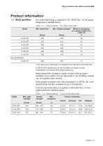
Piling Handbook, 8th edition (revised 2008) Product information 1.3 Steel qualities Hot rolled steel piling is supplied to EN 10248 Part 1 to the grade designations detailed below. Table 1.3.1 Steel qualities - Hot rolled steel piles Minimum elongation on a gauge length of L0 = 5.65 √S0 % * The values in the table apply to longitudinal test pieces for the tensile test. S 460 AP (Mill specification) is also available but please contact ArcelorMittal Commercial RPS before specifying. Steel grades with increased copper content offering higher durability in the splash zone as discussed in the Durability...
Open the catalog to page 8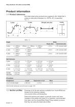
Piling Handbook, 8th edition (revised 2008) Product information 1.4 Product tolerances Hot rolled sheet piling products are supplied to EN 10248 Part 2 unless an alternative standard (i.e. ASTM, JIS ) is specified. Fig 1.4 Z piles Width Single piles Interlocked piles Wall thickness Z piles U piles H piles Straight web piles Cold formed tolerances can be found on page 1/50 Drawings of all the pile sections available from ArcelorMittal are located at the following website www.arcelormittal.com/sheetpiling Sheet pile sections are subject to periodic review and minor changes to the profile may result....
Open the catalog to page 9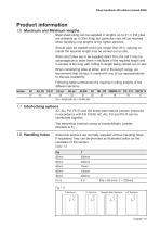
Piling Handbook, 8th edition (revised 2008) Product information 1.6 Maximum and Minimum lengths Steel sheet piling can be supplied in lengths up to 31 m (HZ piles are available up to 33m long) but particular care will be required when handling long lengths of the lighter sections. Should piles be needed which are longer than 31m, splicing to create the required length may be carried out on site. When short piles are to be supplied direct from the mill it may be advantageous to order them in multiples of the required length and in excess of 6m long with cutting to length being carried out on site....
Open the catalog to page 10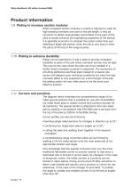
Piling Handbook, 8th edition (revised 2008) Product information 1.9 Plating to increase section modulus When increased section modulus or inertia is required to cater for high bending moments over part of the pile length, it may be economic to attach appropriately sized plates to the pans of the piles to locally enhance the engineering properties of the section. It is generally economic to consider this option rather than just selecting a larger pile section when the pile is very long or when the pile is at the top of the range anyway. 1.10 Plating to enhance durability Plates can be attached...
Open the catalog to page 11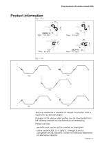
Piling Handbook, 8th edition (revised 2008) Product information Technical assistance is available on request to ascertain what is required for a particular project. Drawings of the various rolled profiles may be downloaded from the following website www.arcelormittal.com/sheetpiling. Please note that: - generally bent corners will be supplied as single piles. - corner sections (C9, C14, Delta13, Omerga18) are not compatible with GU sections. Contact our technical department for alternative solutions. Chapter 1/7
Open the catalog to page 12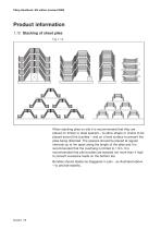
Piling Handbook, 8th edition (revised 2008) Product information 1.12 Stacking of sheet piles Fig 1.12 When stacking piles on site it is recommended that they are placed on timber or steel spacers – to allow straps or chains to be placed around the bundles – and on a level surface to prevent the piles being distorted. The spacers should be placed at regular intervals up to 4m apart along the length of the piles and it is recommended that the overhang is limited to 1.5m. It is recommended that pile bundles are stacked not more than 4 high to prevent excessive loads on the bottom tier. Bundles should...
Open the catalog to page 13All ARCELORMITTAL Long catalogs and technical brochures
 Slim-Floor
40 Pages
 ACB® and Angelina® beams
64 Pages
 Bridges With rolled sections
52 Pages
 Bars and Rods
36 Pages
 Stainless steel in construction
68 Pages
 Arval Sunstyl
16 Pages
 Pflaum & Söhne Bausysteme GmbH
72 Pages
 Arval Colorissime
10 Pages
 Steel Sheet Piling
56 Pages
 Beam Finishing
8 Pages
 ACB - Cellular Beams
48 Pages
 RESIDENTIAL BUILDINGS
68 Pages
 Angelina TM beams
38 Pages
 Safety Barriers
12 Pages
 Pfl aum & Söhne Bausysteme GmbH
72 Pages


Archived catalogs
 Aluzinc® in Building
8 Pages
 Colorissime
10 Pages
 Long Products
180 Pages
 Form Tie Bars
2 Pages
 ExpandedMetal
24 Pages
 CARRIL / RAIL
28 Pages
 AMCRPS
52 Pages
 Sections and Merchant Bars
244 Pages
 arival system by arcelormittal
80 Pages
 Sunstyl
16 Pages
 Floor systems guide
96 Pages
 Material Selection Guide
23 Pages


