- Catalogs
- ARCELORMITTAL Long
- ACB - Cellular Beams
ACB - Cellular Beams
1 /48Pages

ACB - Cellular Beams
1 /48Pages
Catalog excerpts

Sections and Merchant Bars Cellular Beams
Open the catalog to page 1
The intelligent solution for long spans
Open the catalog to page 2
4. Tolerances of ACB® beams 5. Symmetrical cellular beams in roofing and metal decking applications 6. Asymmetric cellular beams in composite floor application 7. Stability in fire and fire safety 8. ACB® design charts 9. Design charts: design examples 11. ACB® beams: a solution for sustainable development 12. AngelinaTM castellated beams with sinusoidal openings Technical assistance & finishing Your partners
Open the catalog to page 3
1. Introduction During more than ten years, there has been an increase in the use of cellular beams, both in metal structures and in exploring new structural solutions. The use of cellular beams allows a new architectural expression. Structures are lightened and spans increased, pulling spaces together. This flexibility goes together with the functionality of allowing technical installations (pipes and ducts) to pass through the openings. The lightweight appearance of cellular beams, combined with their high strength, never ceases to inspire architects to new structural forms. Progress has now...
Open the catalog to page 5
2. Application fields 1. Roofing The use of ACB® as roofing elements enables large spans, in the region of 40 metres, to be covered. Whether used as independent elements (simply supported beams) or continuity elements (frame rafter), the competitiveness of the ACB® solution is confirmed both by the retention of the functionalities of lattice beams and by the reduction of on-site interventions for assembly. ACB® beams offer architects attractive and practical solutions in terms of use of space without screening effect. The diameter of the openings can reach 80 % of the total height of the beam...
Open the catalog to page 6
Figure 2: Renovation using ACB® cellular beams 3. Special applications 3.1. Renovation In order to preserve the architectural heritage, light and flexible structures, based on ACB® cellular beams, are used to strengthen, reuse and modernise old buildings (fig 2). 3.2. Columns and façade elements An application of surpassing elegance is represented by the ACB® column beams (fig 3). Their maximum effect is achieved in applications with low axial load. 3.3. Beams in car parks There are four reasons for recommending the use of ACB® cellular beams for building car parks where no special fire resistance...
Open the catalog to page 7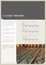
3. Concept – fabrication ACB® beams are fabricated in modern installations on site of ArcelorMittal’s rolling mill for heavy sections at Differdange (Luxembourg). The proximity of these installations limits transport, maximises responsiveness and contributes to the competitiveness of the manufacturing costs. The patented method used for the fabrication of ACB® cellular beams is based on the exclusive use of hot rolled sections. Figure 4: Diagram of the fabrication of an ACB® beam Stage 1: flame cutting Stage 2: separation of T-sections A double cut-out is made in the web by flame cutting. The...
Open the catalog to page 8
Fabrication of ACB® beams 1. Choice of diameter and spacing of openings For a given starting section, there are endless possible combinations of diameters and spacings of openings (fig 6). The choice is subject to the following principle. The final adjustment of the spacing by a few millimetres enables end cut-outs in the full width to be obtained. Figure 6: Definition of an ACB® beam Objectives: Optimisation of the height/ weight ratio Objectives: Optimisation of the load/ weight ratio Starting section (height h) Starting section (height h) Applications: Roofing Gangways/footbridges Wide-span...
Open the catalog to page 9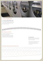
2. Choice of longitudinal profile 2.1. Curved or cambered cellular beams It is easy, during fabrication, to bow the two T-sections (before welding together) to obtain curved or cambered cellular beams without great additional cost (fig 7). Figure 7: Example of a curved ACB® beam The camber is sufficiently marked to avoid any risk of inverted installation. It is particularly suitable for the optimisation of floor beams. The shape imposed remains remarkably stable, even after galvanisation. 2.2. Tapered beams Tapered sections can easily be obtained by inclining the cutting line and reversing one...
Open the catalog to page 10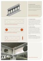
2.3. Asymmetric beams Asymmetric beams are particularly suitable for composite functionality (in combination with the floor slab) and are obtained by joining T-sections of different cross sections or steel grades (fig 9). Cellular beams make a major contribution to the construction of composite floors. Figure 9: Example of asymmetric ACB® beam Figure 10: Example of ACB® beam with elongated opening Figure 11a: Example of ACB® beam with filled openings 2.4. Elongated openings It is sometimes necessary to open up the space between two openings. So far as possible, this elongation should be positioned...
Open the catalog to page 11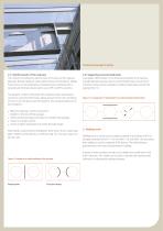
Partially closed openings for jointing 2.7. Reinforcement of the web post The criterion of satisfactory performance at the service limit requires adequate flexural rigidity to reduce deformations and vibrations. Cellular frameworks can be optimised by increased inertia combined with a reduced web thickness favouring the use of IPE and IPE A sections. The designer is often confronted with situations where optimisation cannot be carried out effectively, taking account of the risk of buckling of one or two web posts near the supports. Four classical solutions can be considered: l 2.8. Supporting...
Open the catalog to page 12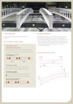
5. Jointing of ACB® beams Examples of ACB® beams that can be ordered are shown in figure 14. When designing the framework, special care should be given to the positions of the openings in order to avoid pointless filling (fig 15). The first step is to optimise the beam from a structural point of view. The second step is to adjust the spacing between openings so as to have a complete web at the ends of the beam. The distance between openings is calculated using the formula: S = L + ao / (n+1) [n = number of openings] l Figure 14: Possibilities for the supply of ACB® beams Outline sketch of ACB®...
Open the catalog to page 13All ARCELORMITTAL Long catalogs and technical brochures
 Slim-Floor
40 Pages
 ACB® and Angelina® beams
64 Pages
 Bridges With rolled sections
52 Pages
 Bars and Rods
36 Pages
 Stainless steel in construction
68 Pages
 Arval Sunstyl
16 Pages
 Pflaum & Söhne Bausysteme GmbH
72 Pages
 Arval Colorissime
10 Pages
 Steel Sheet Piling
56 Pages
 Beam Finishing
8 Pages
 RESIDENTIAL BUILDINGS
68 Pages
 Angelina TM beams
38 Pages
 Safety Barriers
12 Pages
 Pfl aum & Söhne Bausysteme GmbH
72 Pages


Archived catalogs
 Aluzinc® in Building
8 Pages
 Colorissime
10 Pages
 Long Products
180 Pages
 Form Tie Bars
2 Pages
 ExpandedMetal
24 Pages
 CARRIL / RAIL
28 Pages
 AMCRPS
52 Pages
 Sections and Merchant Bars
244 Pages
 arival system by arcelormittal
80 Pages
 ArcelorMittal Piling Handbook
368 Pages
 Sunstyl
16 Pages
 Floor systems guide
96 Pages
 Material Selection Guide
23 Pages


- Industrial flooring
- Tertiary flooring
- ARCELORMITTAL coating
- ARCELORMITTAL building coating
- Indoor coating
- Profiled sheet
- Acoustic floor covering
- Strip flooring
- ARCELORMITTAL outdoor coating
- Interior panel
- Steel sheet metal
- Commercial panel
- Home panel
- Facade profiled sheet
- Metal profile
- Building panel
- Smooth coating
- ARCELORMITTAL protective coating
- Smooth panel