- Catalogs
- Ancon Building Products
- 04a_-_Ancon_Thermal_Windpost_TWP2
04a_-_Ancon_Thermal_Windpost_TWP2
1 /2Pages

04a_-_Ancon_Thermal_Windpost_TWP2
1 /2Pages
Catalog excerpts

Installation Guide Thermal Windpost TWP2 Ancon Thermal Windpost TWP2 Panels of masonry with openings or very large masonry panels can be difficult to design. Ancon Thermal Windposts are designed to span vertically between floors to provide additional lateral support for panels of masonry. Ancon Thermal Windposts are also designed to limit the transfer of thermal energy through the post and to aid the fitting of insulation around the post to maintain the insulation line. Top & Bottom Connections Top and bottom connections are designed with slotted holes to allow adjustment. Where cast-in channels are used parallel to the slab edge, a serrated pad and washer must be provided. Where expansion bolts are used, round holes or slots parallel to the slab edge will suffice. The top connection should also have a vertical slot or slots (no serrations) to permit movement of the frame. Connections to the structural frame are determined prior to Manufacture/Supply, therefore the following rules should be followed. 1. Only use the fixings supplied, as these are integral to the design. Use all normal/serrated washers provided, and tighten nuts to specified tightening torques (see Installation Guide—Bolts). Dimensional positioning of the windpost should be to either Structural Engineers or Specialist details. Ensure all windposts are installed vertical in both planes, thus allowing the ties to slide in the slots if expansion/ contraction of the frame occurs. Top connection - Section (side) view Top connection - Elevation (front) view If the top connection of the windpost cannot be fixed to the structure upon initial placement of the windpost, it may be necessary to provide temporary support or a prop to hold the top of the windpost in place during construction, until such time that the top connection can be fixed. Insulation Installation Cavity wall insulation should be butted hard up to each side of the post and, where the type of insulation allows, taped to the post using a suitable insulation tape. Designs for partial-fill insulation are based around the outer flange being level with the outside face of the insulation (maximum insulation depth 185mm). The post should be positioned a minimum of 50mm from the outer leaf for both partial and full-fill cavities. In full-fill scenarios it is necessary to carefully cut insulation to fit in front of the post between the flange and the brick, ensuring there are no remaining gaps between adjacent pieces of insulation, or between insulation and post. Bottom connection - Plan view Bottom connection Elevation (Front) view
Open the catalog to page 1
Tie Installation and Embedment Wall ties should be fitted in each slot and have a minimum embedment of 50mm into each leaf. Leviat suggest tie lengths which achieve a recommended embedment of between 62.5mm and 75mm, allowing for tolerance on cavity variations Ties for the inner leaf (solid mortar joint) End of block “buttered up” on hem side of post The hem side of the post and the end of the block should be “buttered up” with mortar to pack out the space between the block and the web of the post. On the flat side of the post, the block should be hard up to the web with a thin layer of mortar...
Open the catalog to page 2All Ancon Building Products catalogs and technical brochures
 Eazistrip
16 Pages
 Tapered Thread Couplers
12 Pages
 MBT MechanicallyBolted Couplers
10 Pages
 Staifix HRT4 Wall Tie
1 Page
 EC2-Compliant Design Method
12 Pages
 Reinforcing Bar Couplers
28 Pages
 Tension and Compression Systems
16 Pages
 Restraint System
4 Pages
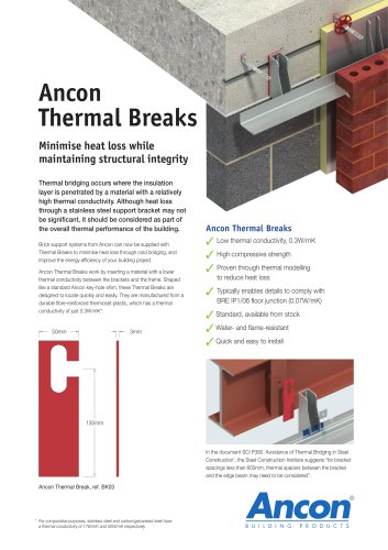 Ancon Thermal Breaks
2 Pages
 Gauge Tape
2 Pages
 Non-Drill Wall Ties
6 Pages
 Refractory Fixings
8 Pages
 Staifix Wall Ties
2 Pages
 Special Fabrications
12 Pages
 Punching Shear Reinforcement
12 Pages
 Starter Bar Systems
8 Pages
 KSN Anchors
24 Pages
 Lockable Dowels
12 Pages
 DSD/ESD Shear Load Connectors
20 Pages
 Masonry Reinforcement
16 Pages
 Tension and Compression Systems
16 Pages
 Corner Guards
2 Pages
 Hidden Strength
7 Pages
 Stainless Steel in Construction
12 Pages
 12 Page Product Guide
12 Pages
 Wall Ties and Restraint Fixings
32 Pages


Archived catalogs
 Windposts and Parapet Posts
8 Pages
 Channel and Bolt Fixings
20 Pages


- Metal fastening system
- Building fastening system
- Building panel
- Exterior mounting clip
- Stainless steel mounting clip
- Construction panel
- Metal panel
- Steel fastening system
- Facade cladding fastening system
- Wall mounting clip
- Ventilated facade fastening system
- Industrial lintel
- Steel panel
- Load-bearing lintel
- Ground anchor
- Shear load connector
- Prefab lintel
- Masonry fastening system
- Reinforcing bar connector
- Wind post