- Catalogs
- Alton greenhouses
- evolution four LT
evolution four LT
1 /52Pages

evolution four LT
1 /52Pages
Catalog excerpts

Instruction Manual Includes Models: 4x4, 4x6, 4x8, 4x10 8 4x12 01/16 Please read all instructions before proceeding
Open the catalog to page 1
4' Deep Evolution Cedar Lean-to Greenhouse Assembly Instructions Section Page Contents: Introduction Base Preparation Overview Base Assembly Front Assembly Door Gable Assembly Plain Gable Assembly Frame Assembly Louvre Assembly Glazing Door Installation Ridge Cover Cap Installation Roof Vent Installation Frame Finishing Gutter and Downpipe Installation Optional Auto Louvre Installation Parts Lists
Open the catalog to page 2
Introduction Thank you for purchasing your new Alton greenhouse. We recommend you familiarise yourself with the instructions and read all safety information before you commence assembly. This instruction manual is also available online at www.greenhousepeople.co.uk in the technical help section should you need to reprint it. Should you require any additional advice you can always call us on 01782 385409. Safety Warning Glass, aluminium and timber can potentially cause injury. Please ensure you wear protective goggles, gloves, headgear and suitable footwear when assembling and glazing the building....
Open the catalog to page 3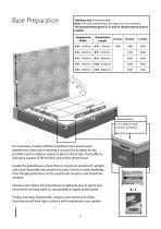
Base Preparation Slab Base Size (Recommended) Note: The base should always be larger than your building. The measurements given in ‘A’ and ‘B’ should only be used as a guide. Greenhouse Width Greenhouse Length Recommended 3’ X 2’ Slab (2” thick) (910mm X 610mm) It is necessary to leave sufficient working room around your greenhouse when you're putting it up and also to allow for the possible need to replace a piece of glass in the future. If possible try and leave a space of 2ft/610mm around the greenhouse. Locate the greenhouse where there is maximum amount of sunlight and avoid if possible...
Open the catalog to page 4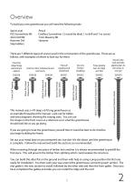
Overview To build you new greenhouse you will need the following tools: Spirit Level PZ2 Screwdriver Bit 4mm Drill Bit Hammer Dril Step ladders Pencil Cordless Screwdriver ( 2 would be ideal, 1 to drill and 1 to screw) 7mm Masonry Bit Hammer There are 7 different types of screws used in the construction of the greenhouse. These are as follows, with examples of where to look out for them: This manual uses a 4 ft deep x 8 ft long greenhouse as an example throughout the manual. Look out for tables and extra diagrams showing the varying sizes. You can use the image on the front cover as a reference...
Open the catalog to page 5
Overview Glazing the structure is very simple but be very careful of the edges of the glass as the pane will break into tiny peaces if you catch an edge on a hard surface such as concrete. You should also wear suitable gloves when handling the glass (this also helps to keep it clean). It is good practice to preload the bar capping with screws and position this around the greenhouse ready for you when you arrive with the glass. During glazing you will also need to fit the louvre vents so make sure you have these built and ready to slot in. These fit between 2 pieces of glass and are held in place...
Open the catalog to page 6
Lay out your aluminium base sections as the diagram shows. Use the joining bracket in each corner to join the sections (diagram 2). The top holes will take a 25mm screw when the side cills are fixed to it. Also attach a joining bracket to the plain gable base section closest to the wall (diagram 3). Next fit the front door cill with 2 plates (HE512M), diagram 1. Part EV0289M can be bolted to the door cill with one of the plates, this might seem odd to start with but once the wall bar is attached and fixed to the wall it will all firm up. Look for the length of building you have in the table below...
Open the catalog to page 7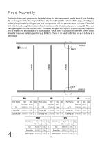
Front Assembly To start building your greenhouse begin by laying out the components for the front of your building flat on the ground like the diagram below. Use the tables at the bottom of the page, identify your building length and this will give you your components with the part numbers and sizes. First of all drill pilot holes through the bottom of each mortise on the cill section (diagram 4, page 9). Then slot each glazing bar into the mortise holes. These are designed as a tight fit so you may need help with this or maybe use a solid object to push against. Once firmly in position fix with...
Open the catalog to page 8
Front Assembly (If you are going to glue your joints this is the first point you would do this. ) Make sure the side bars are pushed all the way in, you may find they need a light tap with a wooden mallet or something similar. Pilot hole, it is easiest to drill down through the middle of the mortise to make sure you get the hole in the correct position
Open the catalog to page 9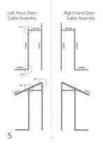
Left Hand Door Gable Assembly Right Hand Door Gable Assembly
Open the catalog to page 10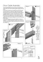
Door Gable Assembly If you have decided to have your door on the left hand gable refer to the left hand door gable assembly and vice versa. As you did with the front assembly lay out the relevant parts face down on a flat area. Again you should drill through the centre of any mortise holes with the drill bit supplied (diagram 7 and 8). First slot the door header (EV0108) onto the gable bars and fix with 50mm screws. Then do the same with the cills. Next drill through the gable bars at the lap joint (diagram 9), fix with 40mm pan head screws. Finally drill through the top of the wall bar as shown...
Open the catalog to page 11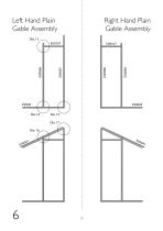
Left Hand Plain Gable Assembly Right Hand Plain Gable Assembly
Open the catalog to page 12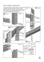
Plain Gable Assembly Lay the parts out flat on the floor again, as you did with the Diagram 13 door gable. Drill and fix the parts in the same way as before but this time use the door header insert (EV0107) in the top mortise holes of the gable bars, diagram 13. You will also use the full length 4ft cill (EV0004). Diagram 15 Keep flush 041 EV0 Screw
Open the catalog to page 13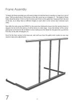
Frame Assembly To begin the frame assembly you will need a helper to hold the front in position or strap it to a set of steps. Drill two pilot holes in the bottom of the side corner bar as in diagram 21. The height of these holes should be about 15mm on the front face and 25mm on the gable face measured from the end of the bar, try to keep these at different heights to each other so the screws don’t intersect each other. Now offer the side corner bar (EV0057) to the eaves bar slotting the tenon into the mortise shown in diagram 20, do not fix this joint as it will be done at a later stage. Screw...
Open the catalog to page 14Archived catalogs
 EVO FUSION 10
44 Pages
 octagonal ssummerhouse
52 Pages
 summerhouse
8 Pages
 OCTAGONAL 10x10
46 Pages