Technical Manual
1 /24Pages

Technical Manual
1 /24Pages
Catalog excerpts
FABRICATION MANUAL A MITSUBISHI POLYESTER FILM
Open the catalog to page 1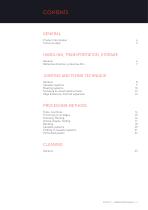
HANDLING, TRANSPORTATION, STORAGE Reflective direction, protective film 7 JOINTING AND FIXING TECHNIQUE Screwing on wood substructures 12 Edge distances, thermal expansion 13 PROCESSING METHODS Groove shapes, folding 17 Folding of cassette systems 21 ALPOLIC™ | FABRICATION MANUAL | 3
Open the catalog to page 3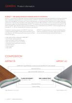
Product information ALPOLICTM – high-quality aluminium composite panels for architecture ALPOLICTM is a brand of the Mitsubishi Chemical Corporation and has been setting trends and standards for building architecture with is exceptional quality products for more than 45 years. ALPOLICTM aluminium composite panels consist of two aluminium sheets which are applied to a mineral core. They are manufactured in a coilcoating process using the most stringent safety and requirements. These are the only panels in the industry that are almost 100% recyclable. In terms of fire protection they provide the...
Open the catalog to page 4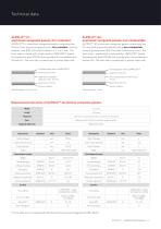
ALPOLIC™ / fr: aluminium composite panels, fire-retardant ALPOLIC™/ fr aluminium composite panels comprising two 0.5 mm thick aluminium panels and a fire-retardant, mineral polymer core (FR). The total thickness is 3, 4 or 6 mm. The front side is coated with a high-quality LUMIFLONTM-based fluoropolymer paint (FEVE) and covered with a removable protective film. The rear side is coated with a primer base coat. ____ Fluoropolymer paint (LUMIFLON™] — Aluminium 0.5 mm — High flame retardant filled core 2.0 - 5.0 mm — Aluminium 0.5 mm Service coating Total thickness: 3, 4 or 6 mm ALPOLIC™ A2: aluminium...
Open the catalog to page 5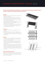
HANDLING, TRANSPORTATION, STORAGE In order to protect ALPOLICTM A2 and ALPOLICTM / fr against mechanical damages caused by transport, storage or handling, the following precautions must be noted. unpacking and repacking the panels, they should be handled in a clean place. • hen stacking or packing the panels, nothing should W be put between them to avoid markings on their surfaces. • hen processing the panels, they should not be handled W on the floor but on a work table. • hen carrying the panels, they should always be handled W by two people. Carry the panels vertically. • hen fabricating the...
Open the catalog to page 6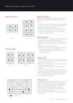
Reflective direction, protective film Reflective direction Horizontal direction Direction arrows are indicated on the protective film of the ALPOLICTM composite panels which specify the reflective direction. • ay P attention to the reflective direction so that no difference in brightness occurs in the overall surface when several panels are arranged on the same level. • n the case of composite panels with a granite or marble I design, the reflective direction must be broken so that the pattern is not repeated. To do so, turn the respective following composite panel by 90°. Vertical direction...
Open the catalog to page 7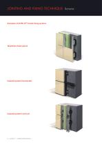
JOINTING AND FIXING TECHNIQUE Examples of ALPOLICTM facade fixing systems Rivet/Face fixed system Cassette system (horizontal) Cassette system (vertical) 8 | ALPOLICTM | FABRICATION MANUAL
Open the catalog to page 8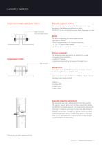
Cassette systems Suspension in bolts and plastic sleeve Cassette systems vertikal Ø 8 mm bolt with Ø 12 mm plastic sleeve The cassettes must be fastened at the longitudinal edges by means of the following subframe on bolts: ALPOLICTM panels with an aluminium sheet thickness of 3 mm Bolts The bolts suspending the above materials are specified as follows: • 8 mm bolts made of A4 stainless steel with Ø Ø 12 x 1.9 Nylon (PA66) sleeves • 10 mm bolts made of A4 stainless steel without sleeves Ø Corner connector The following materials have to be used as the corner connector of the cassettes: • ALPOLICTM...
Open the catalog to page 9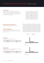
Substructures The support profiles of the substructures for the rivet systems must be aluminum profiles with a thickness of at least 2.0 mm with a tensile strength Rm s 245 N / mm2 and an elastic limit RP 0.2 s 200 N / mm2 (alloy EN AW-6063 T66 in accordance with DIN EN 755-2). Specifications for riveted systems Following details are specified in riveted systems. Fixed and sliding points When attaching ALPOLIC™ composite panels, ensure that there is sufficient allowance for expansion and create fixed and sliding points. Fixed points Take into account at least one fixed point. 10 | ALPOLIC™ |...
Open the catalog to page 10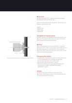
Blind rivets For fastening the ALPOLICTM panels to the above connector, the following blind rivet must be used: Aluminium blind rivet with Ø 5 mm with Ø 11, Ø 14 or Ø 16 mm stainless steel mandrel shaft Supplier: Gesipa / SFS • MBE GmbH • Ipex GmbH • Installation of riveted systems ALPOLICTM panels can be fastened to the substructure by the blind rivet. To prevent tension from occurring at the riveting point, following techniques are specified. Special-purpose gauge tip Note: To avoid galvanic corrosion on ALPOLICTM composite panels, all rivets, screws or nuts used for the connection must be...
Open the catalog to page 11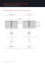
JOINTING AND FIXING TECHNIQUE Screwing on wood substructures Sliding and fixed points for the screw attachment on a wood substructure Sliding point Sliding point attachment with sealing ring Fixed point Fixed point attachment with seal + sleeve Façade centring sealing ring Ø 14 mm x 4 mm Façade centring sealing ring Ø 14 mm x 4 mm Fixed point sleeve Ø 5.8 x 3.5 mm borehole Ø 5.1 mm Façade centring sealing ring Ø 14 mm x 4 mm Ø 14 Fixed point sleeve Ø 5.8 x 3.5 mm borehole Ø 5.1 mm Ø 8.5 Material: TPE, Shore hardness D: 35 acc. to DIN ISD 769 12 | ALPOLICTM | FABRICATION MANUAL
Open the catalog to page 12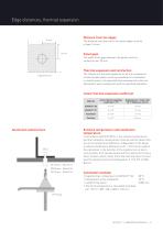
Distance from the edges The distance from the rivet to the panel edges must be at least 16 mm. Panel gaps The width of the gaps between the panels must be limited to max. 20 mm. Thermal expansion and contraction The influence of thermal expansion on all the components of each facade system must be considered. For examples, in riveted system, the expected thermal expansion has to be absorbed at each riveted point with the specified diameters. Linear thermal expansion coefficient Material Extreme temperature and installation temperature In accordance with DIN 18516-1, the extreme temperatures and...
Open the catalog to page 13All ALPOLIC™ catalogs and technical brochures
 Color Chart reAL anodised
8 Pages
 Datasheet: ALPOLIC™/fr
2 Pages
 Datasheet: ALPOLIC™ A2
2 Pages
 Color Chart Classic
6 Pages
 ALPOLIC BE.SAFE EN
7 Pages
 Datasheet: ALPOLIC™ A1
2 Pages
 Color Chart Color the world
8 Pages
 INNOVATIONS 2017
12 Pages
 Datasheet: ALPOLIC™ A2
2 Pages


- Rainscreen cladding
- Panel rainscreen cladding
- Metal cladding
- Smooth rainscreen cladding
- Decorative cassetta
- Gray cassetta
- Aluminum façade cladding
- Metal look cladding
- Textured cladding
- Ventilated facade rainscreen cladding
- Composite cladding
- Brown cassetta
- Interlocking cladding
- Beige cassetta
- Black cassetta
- UV-resistant cladding
- Silver-colored cassetta
- Impact-resistant cladding
- Commercial composite panel