- Catalogs
- Afitexinov
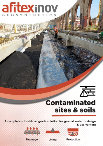
- CUT SLOPES AND WATER MANAGEMENT WITH GEOCOMPOSITES
- Company
- Products
- Catalogs
- News & Trends
- Exhibitions
CUT SLOPES AND WATER MANAGEMENT WITH GEOCOMPOSITES

CUT SLOPES AND WATER MANAGEMENT WITH GEOCOMPOSITES
The document discusses two road construction projects near Paris: a 14-kilometer bypass around Beauvais and the widening of the RN 104 road. These projects aimed to improve traffic flow and involved complex hydro-geotechnical conditions. A drainage technique using polypropylene needle-punched geocomposite with mini-drains was selected to manage groundwater and pore pressure effectively.
Geocomposite Solution Design
The geocomposite solution was designed to replace traditional drain masks, providing advantages in stable embankments that require improved drainage. The structure includes a polypropylene non-woven needle-punched filter layer, mini-drains, and a drainage layer. The design process utilized LYMPHEA software to optimize filtration and drainage configurations.
Construction and Installation
The installation involved unrolling the geocomposite on the embankment and securing it with concrete iron rods. Longitudinal joints were overlapped by at least 10 cm. An anchorage trench was designed to manage strains, and a trench collector was constructed with permeable coarse material to handle water infiltration.
Case Studies
Beauvais Bypass – RN31: This project managed groundwater in a region with complex geological layers by installing a drainage cover over clay layers, ensuring stability through slope stability calculations.
Corbeille Essonne – RN104 Widening: The project involved reshaping the cut slope for stability, with a drainage geocomposite installed to ensure long-term stability and a final slope configuration of 3H/2V.
Conclusion
The use of drainage geocomposites with mini-drains was effective in achieving long-term stability of high cut slopes, offering savings in construction time and materials while integrating the slopes into the landscape.
Catalog excerpts

EuroGeo4 Paper number 115 1 CUT SLOPES AND WATER MANAGEMENT WITH GEOCOMPOSITES Rabah Arab1, Pierre Gendrin2 & Moulay I. Zerhouni3 1 Afitex. (e-mail: [email protected]) 2 Georoute. (e-mail: [email protected]) 3 Fondasol. (e-mail: [email protected]) Abstract: Two road construction projects were carried out near Paris in France. The first project was a 14- kilometer long, 3-lane by-pass road, built to help improve the traffic flow around Beauvais in the north of Paris. The second project was the widening of the existing RN 104 road in the south of Paris. The most important aspects of these projects were the scope of the earthworks required under complex hydrogeotechnical conditions. They involved temporary cut slopes excavated in fine grained soils with steep slopes greater than 10 meters in height. Taking into account the presence of water in the soil, a classical weight draining mask was first considered. However, to allow a reduction in the materials and construction time required, a drainage technique using polypropylene needle-punched geocomposite equipped with mini-drains was chosen to be used alongside other techniques. The aim of the paper is to present the hydro-geological and the geotechnical context of the two projects and discuss the adopted drainage geocomposite solutions used to address the encountered difficulties with ground water and pore pressure management at some key sections of the two projects. Keywords: cut slope, drainage, filtration, geocomposites, design, landscaping INTRODUCTION The greater demand for road developments to improve the traffic flow, particularly around large, cities requires the creation of bypass roads or the widening of the existing highways. These developments present numerous technical constraints to be considered alongside the economic necessity of construction cost and reducing traffic delays. The asset owner is constantly in search of solutions to enable the widening of road carriageways by increasing embankment slope angles. This paper examines the management of waters in an excavation slope by drainage using geocomposites to reduce the interstitial pressures and to improve the safety factor against failure of the slope and eliminating erosion. In the presented cases, we have used a geocomposite for drainage combined with regularly drilled mini-drains. CONCEPTION AND DESIGN OF THE GEOCOMPOSITE SOLUTION Principle of drain mask Water inflow in natural or man-made slopes considerably reduces stability and often causes failure. Several methods of slope drainage are possible. The traditional drain mask method using stones or coarse materials is one of them. Often a drain mask fulfils two objectives: • Improves mechanical stability as a result of its weight, • Improves drainage as a result of the permeability of the material. A geocomposite solution may be advantageous in replacing the traditional drain mask in the two following cases: • Where the embankment is stable without additional weight but water infiltration and water inflow may cause instabilities and failure, • Where the material added can fulfil the mechanical function but not the hydraulic function. Drainage geocomposite structure The solution used to replace the traditional system is shown in Figure 1, it consists of a drainage geocomposite with a structure composed of: • a polypropylene non-woven needle-punched filter layer (filter 1) ; • polypropylene mini-drains, perforated at regular intervals on two axes at 90° (2 perforations per rib) ; • a polypropylene non-woven needle-punched drainage layer; • a polypropylene non-woven needle-punched filter layer (filter 2). The various components are industrially bonded with needle-punching process. It is widely used in geotechnical and geoenvironnemental projects (Arab et al., 2002, 2004, 2006) (Gendrin et al. 2002).
Open the catalog to page 1
EuroGeo4 Paper number 115 2 Figure 1. Structure SOMTUBE FTF geocomposite Design of the drainage system The design of the drainage system has to take into account the filtration aspects and the in situ discharge capacity of the product and the drain or the trench collector. Filtration The filter opening size is 80 ìm and is compatible with the underlying beds according to the French standard NF G 38061. The two filters are made of needle-punched, non-woven geotextiles specially adapted to the task of filtering. The mechanical bonding of filter and drainage layers helps avoid all risk of slip between...
Open the catalog to page 2
EuroGeo4 Paper number 115 3 For practical reasons (wind resistance, accessibility, etc.), the drainage geocomposite was fastened to the slope using concrete iron rods, for example (Figure 3). Transversal joints (end to end) were not permitted on the slope face. The longitudinal joints were created by overlapping the layers by a minimum of 10 cm. Figure 3. Drainage geocomposite fixation on the slope Anchorage trench design The strains sustained by the geocomposite in the anchoring trench (Figure 4) are function of: • The shear resistance geocomposite/embankment, ôs • The Shear resistance in situ...
Open the catalog to page 3
EuroGeo4 Paper number 115 4 Trench collector Trench design consists of dimensioning the geocomposite by determination of the water infiltration rate by linear meter of drain down the slope. This value prescribes the minimum internal diameter for the road drain that requires installation in the drainage trench. The trench collector was constructed using permeable coarse material, usually gravel type 20/40 (grain size distribution), protected by filter geotextile. The connection of the drainage geocomposite and drain collector at the foot of the slope was achieved with a simple hydraulic overlap...
Open the catalog to page 4
EuroGeo4 Paper number 115 5 Table 1. Classifications to GTR 92 and geotechnical characteristics of the formations Formations Passes as 80 ìm (%) Water content w (%) Plasticity index Soil blue values VBS Classification GTR Cohesion c‘(kPa) Friction angle ö‘ (°) Sandy clay 23 - 37 11 - 29 14 – 20 0.4 – 1.6 A1/A2/B5 c‘ = 1.2 kPa ö‘ : 33° Silt and marl clay 58 – 96 10 - 31 12 -24 - A1/A2 c‘ = 15 - 23 kPa ö‘ : 19 - 31° Green sand Albian 4.7 – 45 4 - 38 - 0.3 – 3.1 B5/B2 c‘ = 14 kPa ö‘ : 30° Plastic and sandy clay 58 – 99 14 -28 22 – 39 - A3/A2/A1 c‘ = 9 kPa ö‘ : 21° Sand and clay clump mix 51 – 91...
Open the catalog to page 5All Afitexinov catalogs and technical brochures
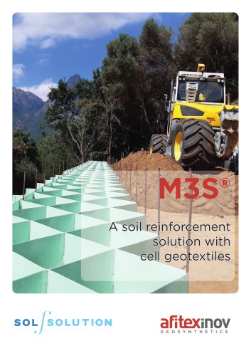 M3S solutions
4 Pages
 Solutions for mining
4 Pages
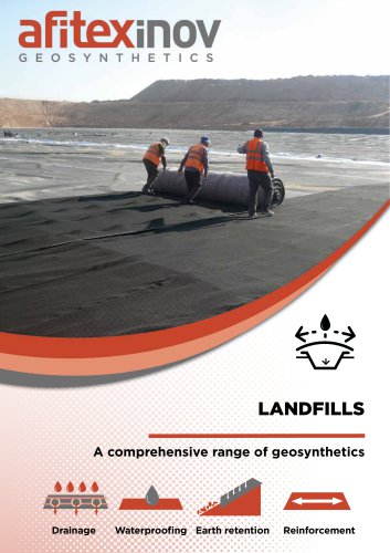 Landfills solutions
36 Pages
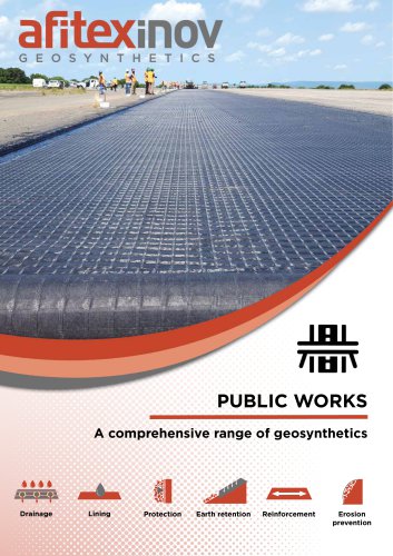 Solutions for Public Works
44 Pages
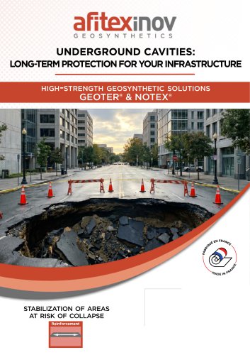 Solutions for cavities
4 Pages

Archived catalogs

- Industrial insulation
- Panel insulation
- Thermal insulation
- Synthetic insulation
- Wall insulation
- Industrial concrete block
- Rigid insulation panel
- Exterior insulation
- Retaining wall
- Solid concrete block
- High-resistance concrete block
- Stone look concrete block
- Industrial geogrid
- Concrete retaining wall
- Public work concrete block
- Modular retaining wall
- Reinforcement geogrid
- Retaining wall concrete block
- Non-woven geotextile