

- Products
- Catalogs
- News & Trends
- Exhibitions
PUFFER – S1

PUFFER – S1
Introduction
This manual targets designers, installers, end users, and maintenance technicians working with PUFFER and PUFFER S1 inertial accumulators. It stresses the importance of qualified personnel performing installation, commissioning, maintenance, and repairs in compliance with local regulations and safety standards.
Description
Application
The PUFFER inertial accumulator, constructed from carbon steel, is designed for heating systems using alternative or recovered energy sources, promoting economic savings. It is also suitable for intermittent heat generators like thermo-fireplaces and solid fuel boilers.
Operation
- Supports temperature stratification via multiple hydraulic connections at different heights.
- Separates primary and secondary hydraulic circuits, allowing expansion of energy sources or user circuits.
- The PUFFER S1 model includes a tubular coil heat exchanger that physically separates system fluid from the alternative energy source.
Construction Features
- Vertical tanks made from ST 37-2 carbon steel compliant with DIN 17100 and DIN 4753.
- Designed for heating water circuits with max operating temperature of 95°C and pressure up to 3 bar.
- Manufactured under PED Directive 97/23/EC and hydraulically tested at 1.5 times max operating pressure.
Product Range
Available in eight models with capacities from 300 to 3000 liters.
Heat Exchanger (PUFFER S1)
Features a spiral-wound carbon steel tubular coil welded to the lower tank section.
External Protection and Insulation
- Tank painted with anti-rust coating; no additional corrosion treatment needed.
- Insulation: rigid closed-cell polyurethane foam (50 mm) for smaller models (300-500 L), flexible open-cell polyurethane foam (100 mm) for larger models (800-3000 L).
- External covering is a flexible black PVC sheath.
Technical Characteristics
Construction Diagram and Connections
Includes detailed schematics for hydraulic connections, sensor ports, safety valves, air vents, and drain valves. PUFFER S1 adds solar coil supply and return connections.
Technical Data Summary
| Model | Capacity (L) | Max Pressure (bar) | Max Temp (°C) | Weight Empty (kg) | Weight with Coil (kg) | Coil Surface (m²) | Coil Max Pressure (bar) | Thermal Output (kW) | Primary Flow (L/h) | Pressure Drop (kPa) | Coil Volume (L) | Coil Weight (kg) |
|---|---|---|---|---|---|---|---|---|---|---|---|---|
| PUFFER 300 | 300 | 3 | 90 | 63 | 85 | 1.5 | 6 | 14 | 600 | 2 | 12 | 22 |
| PUFFER 500 | 500 | 3 | 90 | 86 | 120 | 2.3 | 6 | 21 | 920 | 4 | 18.5 | 34 |
| PUFFER 800 | 800 | 3 | 90 | 130 | 175 | 2.8 | 6 | 26 | 1120 | 5 | 22.5 | 45 |
| PUFFER 1000 | 1000 | 3 | 90 | 145 | 190 | 3.0 | 6 | 28 | 1200 | 6 | 24 | 45 |
| PUFFER 1500 | 1500 | 3 | 90 | 220 | 270 | 4.0 | 6 | 37 | 1600 | 8 | 32 | 50 |
| PUFFER 2000 | 2000 | 3 | 90 | 250 | 325 | 4.5 | 6 | 42 | 1800 | 10 | 36 | 75 |
| PUFFER 2500 | 2500 | 3 | 90 | 300 | 390 | 5.0 | 6 | 47 | 2000 | 12 | 40 | 90 |
| PUFFER 3000 | 3000 | 3 | 90 | 350 | 450 | 6.0 | 6 | 56 | 2400 | 18 | 50 | 100 |
Key Data: All models operate at max 3 bar pressure and 90°C temperature. Coil max pressure is 6 bar. Thermal output ranges from 14 kW (PUFFER 300) to 56 kW (PUFFER 3000). Primary flow rates and pressure drops increase with capacity.
Dimensions
Diameter ranges from 650 mm (smallest model) to 1450 mm (largest). Heights vary from 1360 mm to 2840 mm. Connection sizes and positions are specified for proper installation.
Installation
Initial Verification
- Confirm operation within specified temperature and pressure limits.
- Ensure heat generator power matches heat exchanger requirements.
Positioning
- Install indoors, protected from weather exposure.
- Locate close to primary heat source.
- Mount on flat, stable surface capable of supporting full weight.
Connections
- Follow installation diagrams as guidelines; system designer must ensure compliance with local standards and manufacturer limits.
- Include appropriately sized expansion vessel.
- Install air vent valves at accumulator top.
- Use filters if water impurities are present.
- Ensure pumps provide adequate flow and pressure.
- Correctly position thermostat and thermometer sensors.
- Ground the accumulator.
- Insulate connecting pipes to minimize heat loss.
- For PUFFER S1, provide drain valve on solar coil return line.
Commissioning
- Must be performed by qualified personnel only.
- Fill accumulator with water respecting max pressure limits.
- Keep air vent valves open during filling to purge air.
- If antifreeze is used, it must be non-toxic and compliant with hygiene standards; consult manufacturer.
- Verify safety valve installation and calibration.
- Check for leaks and proper air vent closure.
- Confirm correct pipe connections.
Maintenance
Periodic User Checks
- Monthly visual inspection of valves, connections, and accessories for leaks or malfunctions.
- Check air vent valve for leaks.
- Contact qualified technician if anomalies occur.
Annual Maintenance
- Performed by qualified technician.
- Check air vent operation and system pressure.
- Test control and safety devices.
- Ensure discharge pipes lead directly to sewer to prevent burns or damage.
- Check for dripping safety groups indicating expansion or valve scaling issues.
Draining Procedures
- Water temperature may exceed 80°C; risk of burns.
- Connect flexible hose to drain valve and empty water into sewer.
- Open air vents to accelerate draining.
- Close valves after draining.
Coil Draining (PUFFER S1)
- Drain coil via dedicated drain valve on solar circuit.
- Open air vent on solar circuit to facilitate draining.
- Close valves after completion.
Additional Notes
Space reserved for further remarks or instructions.
Document Information
Origin: Pana, Faenza (RA), Italy. Contact: Tel. 0546 646144, Fax 0546 646150, Email: [email protected], Website: http://www.acv.com.
Version: 01 dated 26 May 2009; initial release 00 on 2 December 2008. No further revisions noted.
Catalog excerpts
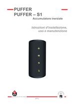
IT ¡ 1 Istruzioni d’installazione, uso e manutenzione PUFFER PUFFER – S1 Accumulatore inerziale
Open the catalog to page 1
IT ¡ 2 SOMMARIO INTRODUZIONE 3 Destinatari 3 Simboli 3 Avvertenze generali 3 DESCRIZIONE 4 Impiego 4 Funzionamento 4 Caratteristiche costruttive 4 Gamma 4 Scambiatore 4 Protezione esterna antiruggine serbatoio 4 Isolamento termico 4 Rivestimento esterno 4 Schemi di impianto 5 CARATTERISTICHE TECNICHE 6 Dati tecnici 7 Dimensioni 7 INSTALLAZIONE 8 Verifica iniziale 8 Posizionamento 8 Allacciamento 8 Connessioni idrauliche 8 MESSA IN SERVIZIO 9 Avvertenze 9 Riempimento dell’accumulatore 9 Verifiche prima della messa in servizio 9 MANUTENZIONE 10 Controllo periodico da parte dell’utente 10 Manutenzione...
Open the catalog to page 2
IT ¡ 3 INTRODUZIONE DESTINATARI Il presente manuale è rivolto a: - il progettista - l’installatore - l’utente che lo riceve in custodia - i tecnici addetti alla manutenzione SIMBOLI In questo manuale vengono utilizzati i seguenti simboli: AVVERTENZE GENERALI • Leggere attentamente questo manuale prima di installare e di mettere in servizio l’accumulo inerziale. • E’ vietato eseguire modifiche all’interno dell’apparecchio senza accordo scritto col costruttore. • Il montaggio, la messa in servizio, la manutenzione e la riparazione vanno eseguiti da un tecnico qualificato in conformità alle normative...
Open the catalog to page 3
IT ¡ 4 DESCRIZIONE IMPIEGO L’accumulatore inerziale PUFFER (PUFFER S1) in acciaio al carbonio è utilizzato in impianti ed in sistemi di riscaldamento ambiente dove è previsto lo sfruttamento di energie alternative o da recupero, con conseguenti risparmi economici. Viene inoltre usato per sfruttare generatori di calore a funzionamento discontinuo come termocamini e caldaie a combustibili solidi. FUNZIONAMENTO Le principali funzioni di questo prodotto, inserito in un impianto sono: - stratificare la temperatura del circuito idraulico e rendere disponibili i vari livelli mediante attacchi idraulici...
Open the catalog to page 4
IT ¡ 5 DESCRIZIONE SCHEMI DI IMPIANTO PUFFER PUFFER – S1
Open the catalog to page 5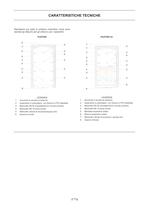
IT ¡ 6 CARATTERISTICHE TECNICHE Riportiamo qui sotto lo schema costruttivo, dove sono riportati gli attacchi per gli utilizzi e per i serpentini. PUFFER 5 1 2 3 4 4 3 3 3 4 4 3 3 3 3 6 LEGENDA 1. Accumulo in acciaio al carbonio 2. Isolamento in poliuretano con finitura in PVC flessibile 3. Manicotto DN 50 mandata/ritorno circuito primario 4. Manicotto DN 15 porta sonda 5. Manicotto valvola di sicurezza/spurgo aria 6. Scarico di fondo PUFFER S1 7 1 2 3 4 4 3 3 3 4 4 3 3 3 3 5 6 8 LEGENDA 1. Accumulo in acciaio al carbonio 2. Isolamento in poliuretano con finitura in PVC flessibile 3. Manicotto...
Open the catalog to page 6
IT ¡ 8 INSTALLAZIONE VERIFICA INIZIALE L’accumulatore è stato progettato, costruito e verificato entro i limiti di temperatura e pressione riportati al capitolo CARATTERISTICHE TECNICHE – DATI TECNICI. Qualsiasi utilizzo fuori dai limiti sopraindicati è da ritenersi non idoneo e pericoloso. Assicurarsi che la potenza termica utile del generatore sia sufficiente per alimentare lo scambiatore del bollitore. POSIZIONAMENTO - Installare l’accumulatore al riparo da agenti atmosferici. - Installare l’accumulatore il più vicino possibile alla fonte di calore primaria (caldaia / pannello solare). - installare...
Open the catalog to page 8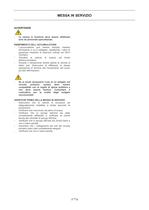
IT ¡ 9 MESSA IN SERVIZIO AVVERTENZE - La messa in funzione deve essere effettuata solo da personale specializzato. RIEMPIMENTO DELL’ACCUMULATORE - L’accumulatore può essere riempito insieme all’impianto a cui è collegato, rispettando i valori di pressione massima di esercizio indicati nei DATI TECNICI. - Chiudere la valvola di scarico nel fondo dell’accumulatore. - Durante il riempimento tenere aperta la valvola di sfiato aria. Assicurarsi di effettuare la stessa operazione al termine del riempimento dal punto più alto dell’impianto. - Se si rende necessario l’uso di un antigelo nel circuito...
Open the catalog to page 9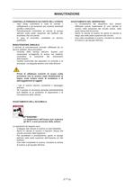
IT ¡ 10 MANUTENZIONE CONTROLLO PERIODICO DA PARTE DELL’UTENTE - Ogni mese controllare a vista le valvole, i collegamenti e gli accessori per scoprire eventuali perdite o disfunzioni. - Periodicamente controllare la valvola di spurgo dell’aria sulla parte superiore del bollitore per accertarsi che non perda. - In caso di anomalia, contattare un tecnico qualificato. MANUTENZIONE ANNUALE Il servizio di manutenzione annuale, effettuato da un tecnico abilitato, deve prevedere: - controllo dello spurgo dell’aria. Questo può comportare un’aggiunta di acqua nel sistema; controllare la pressione dal manometro...
Open the catalog to page 10
IT ¡ 12 ACV ITALIA Srl - Via Pana, 92 48018 FAENZA (RA) Tel. 0546 646144 Fax. 0546 646150 Home page: http://www.acv.com E-mail : [email protected] 01 26/05/2009 00 Prima emissione 02/12/2008 REVISIONE MODIFICHE DATA
Open the catalog to page 12All ACV catalogs and technical brochures
 RASTRELLIERA CURVE
2 Pages
 PRODUCTS OVERVIEW 2019
28 Pages
 E-TECH
7 Pages
 LARGE CAPACITY TANKS
4 Pages
 COMPACT CONDENS
2 Pages
 WATERMASTER
2 Pages
 Smart Line & SLEW
2 Pages
 Smart ME
2 Pages
 Heliosplan S
52 Pages
 ACV products 2014
20 Pages
 Comfort
4 Pages
 Room Thermostat
2 Pages
 HeatMaster
2 Pages
 Mini Brochure
26 Pages
 Product Overview 2013
20 Pages



Archived catalogs
 SolarMaster
16 Pages
 etech p
27 Pages
 deltapro & pro pack
26 Pages
 Compact A
18 Pages
 alfa
alfa2 Pages
 alfaF - FV
2 Pages
 Mini-catalog ACV 2007
10 Pages
- Indoor boiler
- Domestic boiler
- Industrial solar panel
- Industrial water heater
- Gas boiler
- Vertical water heater
- Electric water heater
- Condensing boiler
- Wall-mounted boiler
- Energy rating boiler
- Wall-mounted water heater
- Free-standing water heater
- Commercial boiler
- Thermal solar collector
- Boiler with water heater
- Flat thermal solar collector
- Thermal solar collector with frame
- Heating thermal solar collector
- Class A boiler