- Catalogs
- 2VV s.r.o.
- VULKAN / VKN-P
VULKAN / VKN-P
1 /4Pages

VULKAN / VKN-P
1 /4Pages
Catalog excerpts

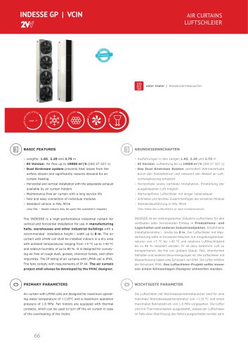
BASIC FEATURES – Installation into a duct – Integrated automatic thermal protection – integrierter automatischer Wärmeschutz – IP 44 rating for electric system The VULKAN VKN-P duct fans are designed for the indoor Die Rohrleitungsventilatoren VULKAN VKN-P sind für den operation for conveying fresh air free of rough dust, grease, Betrieb in Innenbereichen, für die Förderung von reiner Luft chemical fumes, and other impurities. The fans are suitable for ohne groben Staub, Fettigkeit, Dämpfe von Chemikalien und installation into HVAC ducts and for other HVAC applications weiterer Verunreinigungen bestimmt. Sie sind geeignet für provided that the parameters of air conveyed are adhered to. den Einsatz in lufttechnischen Verteilungen und ggf. anderen lufttechnischen Anwendungen, sofern die Parameter der geförderten Luft eingehalten sind. PRIMARY PARAMETERS
Open the catalog to page 1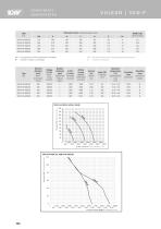
COMPONENTS KOMPONENTEN VULKAN I VKN-P Type DN - corresponds to nominal diameter of ducting. DN - Nenndurchmesser der angeschlossenen Rohrleitung. N* -numberofholesintheflange N - Lochzahl im Flansch
Open the catalog to page 2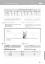
VULKAN I VKN-P INSTALLATION UND MONTAGE - Thefancanbe installed in any position (axis inavertical directionisrecommended). - Hanged installation intoa duct - die Einbauposition des Ventilators ist in beliebiger Stellung moglich (empfohlene Stellung ist mit der Achse in waage-rechter Stellung) - Einbau in Rohrleitungen mit Flansch CONTROL BEDIENUNG The VULKAN VKN-P fans are not fitted with an integrated speed control system. The fan speed is controlled by reducing the supply voltage. The fans cannot be controlled by a frequency converter. Recommendedspeed controller types Die Ventilatoren VULKAN...
Open the catalog to page 3
OPTIONAL ACCESSORIES WÄHLBARES ZUBEHÖR Speed controller Speed controller WIRING DIAGRAMS ELEKTRISCHE SCHALTPLÄNE All the wiring diagrams included in the catalogue are only in- Sämtliche im Katalog angeführten Schaltpläne sind nur informativ. formative. When assembling the product, observe strictly the Bei der Montage des Produktes richten Sie sich ausschließlich nach den Schild-werten und Schaltbildern, die entweder auf directly to the product or enclosed to the product. dem Produkt angebracht oder zum Produkt beigelegt sind. Wiring diagram
Open the catalog to page 4All 2VV s.r.o. catalogs and technical brochures
 ALFA 95 FLAT_2024
19 Pages
 TECHNICAL CATALOG 2022
619 Pages
 AIR CURTAINS
7 Pages
 SAVANA EC
12 Pages
 2VV Brochure
19 Pages
 VIREX AIR
4 Pages
 FINESSE EC
14 Pages
 INDESSE GP / VCIN
18 Pages
 ENTRESSE
10 Pages
 ALFA 95 FLAT
19 Pages
 HEAT RECOVERY UNITS
7 Pages
 STANDESSE XP
8 Pages
 STANDESSE XP VCST5D
15 Pages
 ALFA EC
39 Pages
 INDESSE EC
19 Pages
 VENESSE
12 Pages
 BASIC
BASIC7 Pages
 INDESSE GP VCIN
17 Pages
 FINESSE
14 Pages
 E S S E N S S E NEO
13 Pages
 INDESSE GP SIMPLY THE BEST
5 Pages
 SAVANA
11 Pages
 VENUS
VENUS13 Pages
 WHISPER AIR
17 Pages
 ALFA 95
29 Pages
 INDESSE
19 Pages
 standesse
21 Pages
 ESSENSSE NEO
20 Pages
 SAVANA
2 Pages
 ESSENSSE NEO EC
2 Pages
 WHISPER AIR
4 Pages
 V E N E S S E
9 Pages
 FINESSE
18 Pages
 S TA N D E S S E
16 Pages
 B A S I C
5 Pages
Archived catalogs


- Mechanical ventilation unit
- Industrial air purifier
- Industrial air heater
- Industrial air curtain
- Commercial air curtain
- Free-standing air purifier
- Industrial air curtain
- Ceiling-mounted air curtain
- Heat recovery unit
- Home air purifier
- Wall-mounted air heater
- Electric air heater
- Dual-flow mechanical ventilation unit
- Residential heat recovery unit
- HEPA filter air purifier
- Disinfection air purifier
- Wall-mounted air curtain
- Home heat recovery unit
- Commercial heat recovery unit
- Compact heat recovery unit