
カタログの抜粋

Quick Start Installation Guide Zip HydroTap G5 Command Centre Boiling/Chilled models AFFIX PRODUCT LABEL HERE Australia UK Visit our website to download the manuals Quick Start Installation Guide 807118 v1.00 01.21 G5 BC Quick Start Guide
カタログの1ページ目を開く
Quick Start Installation Guide 807118 v1.00 01.21 G5 BC Quick Start Guide
カタログの2ページ目を開く
SECTION 1: Using these instructions This document is a Quick Start Installation Guide. For further details on installing and operating your HydroTap download & read the Command Centre installation and user instructions , which can be found online at: (Australia) www.zipwater.com (UK) specify.zipwater.co.uk Read and use the instructions supplied with individual kit components for a safe installation. Hot surface Highly Flammable Explanation of symbols A ! Read the WARNING Danger of instructions electric shock Quick Start Installation Guide 807118 vl.00 01.21 G5 BC Quick Start Guide
カタログの3ページ目を開く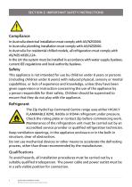
SECTION 2: IMPORTANT SAFETY INSTRUCTIONS ! Compliance In Australia electrical installation must comply with AS/NZS3000. In Australia plumbing installation must comply with AS/NZS3500. In Australia For residential chilled models, all refrigeration must comply with AS/NZS 60335.2.24. In the UK the system must be installed in accordance with water supply byelaws, current IEE regulations and local authority byelaws. Safety This appliance is not intended for use by children under 8 years or persons (including children under 8 years) with reduced physical, sensory or mental capabilities, or lack...
カタログの4ページ目を開く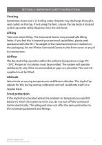
SECTION 2: IMPORTANT SAFETY INSTRUCTIONS Venting Sometimes steam and / or boiling water droplets may discharge through a vent outlet on the tap. If not using the font, ensure the tap body is located so the tap outlet safely dispenses into the sink bowl. Lifting Take care when lifting. The Command Centre may exceed safe lifting limits. If you feel this is beyond your personal capabilities, please seek assistance with the lift. The weight of the Command Centre is marked on the packaging. Do not lift the Command Centre by the front cover or any of its connections. Airflow The Zip HydroTap...
カタログの5ページ目を開く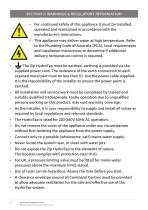
SECTION 3: WARNINGS & REGULATORY INFORMATION • For continued safety of this appliance it must be installed, operated and maintained in accordance with the manufacturer’s instructions. • This appliance may deliver water at high temperature. Refer to the Plumbing Code of Australia (PCA), local requirements and installation instructions to determine if additional delivery temperature control is required. The Zip HydroTap must be earthed, earthing is provided via the supplied power cord. The resistance of the earth connection to each exposed metal part must be less than 1Ω. Use the power cable...
カタログの6ページ目を開く
SECTION 3: WARNINGS & REGULATORY INFORMATION • Valve and fitting threads must be sealed appropriately with PTFE tape where compression seals are not provided. • Always flush new filter before use. • Do not connect Booster to electrical supply until commissioning. • Do not over tighten plumbing and hose connections. • Braided hoses supplied cannot be lengthened. • The power cord and general power outlet must be in a safe and accessible position after installation. When positioning the appliance, ensure the power supply cord is not trapped or damaged. If the power supply cord is damaged it...
カタログの7ページ目を開く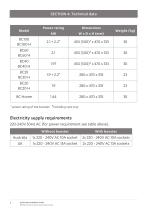
SECTION 4: Technical data Quick Start Installation Guide 807118 v1.00 01.21 G5 BC Quick Start Guide
カタログの8ページ目を開く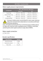
SECTION 4: Technical data Quick Start Installation Guide 807118 v1.00 01.21 G5 BC Quick Start Guide
カタログの9ページ目を開く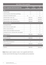
SECTION 5: Parts supplied Parts supplied with the HydroTap HydroTap pipes, tubes hoses and fittings Separate vented Mixer tap kit Separate Mains mixer Tap Separate Mains mixer Tap fittings Separate Mains mixer Tap instructions Command Centre Mains electrical supply cable Water supply inlet hose Water supply inlet adaptor and strainer Ventilation kit (inc. vent tray 100 -40 models) Command Centre Water block kit Booster Booster & hoses Filters Water filter & instructions Limescale filter kit Font Font kit Note: Mains water isolation valve is not supplied with the kit. Contact Zip for the...
カタログの10ページ目を開く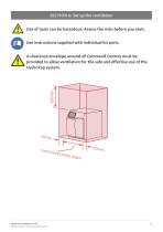
Use of tools can be hazardous. Assess the risks before you start. Use instructions supplied with individual kit parts. A clearance envelope around all Command Centres must be provided to allow ventilation for the safe and effective use of the HydroTap system. Quick Start Installation Guide 807118 v1.00 01.21 G5 BC Quick Start Guide
カタログの11ページ目を開く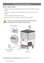
BC100 - BC40 models • Cold air is drawn in through the inlet vent and gap provided by the door buffers. • Inlet vent is mounted over cupboard side, door or floor cut-out (see below). • Warm air is exhausted through vent tray. • Observe 100mm inlet / outlet vent separation (see below). The vent tray must be fitted. It provides a safe exhaust for refrigerant gas in the unlikely event of a leak. Air inlet options 4mm door buffers (supplied) Air outlet Vent tray Vent tray dimensions WxDxH (mm): 500 x (515-555) x 40 12 Quick Start Installation Guide 807118 v1.00 01.21 G5 BC Quick Start
カタログの12ページ目を開く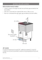
BC30, BC20 & Home models • Cold air is drawn in through the inlet vent and lower gap provided by the door buffers. • Inlet vent is mounted over cupboard side, door or floor cut-out. • Warm air is exhausted through upper gap provided by the door buffers. 4mm door buffers (supplied) Air inlet Inlet vent All models If cupboard temperature exceeds 35°C, additional ventilation is required. Contact your Zip service provider for options (including additional vents and fan kit). Quick Start Installation Guide 807118 v1.00 01.21 G5 BC Quick Start Guide
カタログの13ページ目を開く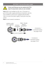
SECTION 7: Connect the water supply Valves and fittings must be sealed with PTFE tape if compression seals are not included. Note Mixer tap installations also use a ‘Tee piece’ as part of the water supply plumbing connections, see the Tap installation instructions supplied with the Mixer Tap to connect the water supply if using the mixer tap option. Note correct strainer orientation. Isolation valve (not supplied) Male - Female adaptor Strainer (supplied) (supplied) Connect to Command Centre, see pages 19,20 Connect together Connect to Command Centre, see pages 19,20 Quick Start...
カタログの14ページ目を開くZipのすべてのカタログと技術パンフレット
-
 Zip Touch-Free
20 ページ
-
 Wall Fountain
2 ページ
-
 Chilltaps
2 ページ
-
 Economaster
2 ページ
-
 Chill Fountain
2 ページ
-
 Chillmaster
2 ページ
-
 Filter Tap
2 ページ
-
 HYDROTAP G4
8 ページ
-
 IHW D
IHW D2 ページ
-
 Econoboil
2 ページ
-
 Zip Rental Brochure
6 ページ
-
 ZIP TUDOR
2 ページ
-
 IHW TMV
2 ページ
-
 Zip M Series
2 ページ
-
 Zip D Series
2 ページ
-
 Zip IHW C Series
2 ページ
-
 Electronic Zip Duo
2 ページ
-
 Zip Sensor Tap
2 ページ
-
 Soap Dispensers
2 ページ
-
 Washroom brochure
20 ページ
-
 Zip HydroTap at Work
32 ページ
-
 Zip HydroTap at Home
32 ページ
-
 Zip Autoboil ®
2 ページ
-
 Zip Chill Tap
2 ページ
-
 Zip AquaSense
2 ページ


