カタログの抜粋
Manuel d’installation Gebrauchsanweisung Installation manual Instrukcja montażu Manuale d’installazione Installatiegids
カタログの1ページ目を開く
CONTENTS GENERAL PRESENTATION 2 SAFETY INSTRUCTIONS 2 PRODUCT DESCRIPTION 2 Product components Area of application POINTS TO CHECK PRIOR TO INSTALLATION 3 Preliminary checks Safety instructions PROGRAMMING 5 Programming button description End limit setting and self-learning Memorising the remote controls for operation in «Total opening» mode OPERATING TEST 5 Using the remote controls Obstacle detection function Built in lighting operation CONNECTING PERIPHERALS 6 Description of the various peripherals Electrical connectio
カタログの2ページ目を開く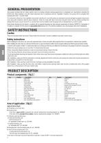
GENERAL PRESENTATION This product complies with the “safety, specific rules for powering vertically opening garage doors in residential use” requirements (standard EN 60335-2.95). When installed in line with these instructions and in compliance with the “Installation Checklist”, the product will be compliant with standards EN 13241-1 and EN 12453. The instructions referred to in the installation manual and instructions for use of this product are designed to prevent damage to property and personal injury along with compliance with the above standards. Failure to comply with these...
カタログの3ページ目を開く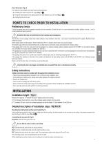
Door dimensions (Fig. 3) For maximum door heights, the motor travel can be optimised: • By installing the motor head at a 90° angle (Fig. 7- • By fixing the lintel bracket to the ceiling, behind the lintel itself by up to 200 mm (Fig. 5- • By cutting the link arm to size. POINTS TO CHECK PRIOR TO INSTALLATION Preliminary checks Check the garage door can be operated manually and runs smoothly. Ensure the door is in good mechanical condition (pulleys, mounts…) and is correctly balanced (spring tension). The structure of your garage (walls, lintel, inside surfaces, cross members, door rails…)...
カタログの4ページ目を開く
Fitting the rail onto the motor head (Fig. 7) Fitting the complete assembly onto the garage ceiling (Fig. 8 to 10) Fitting to the lintel bracket (Fig. 8) Ceiling mounting F • lush with the ceiling: mount the system directly onto the ceiling using the rail (Fig. 9). It is possible to add mounting points at the motor head level (Fig. 9- ). • ung from the ceiling: two options: H - mount the system at the motor head (Fig. 10- a ). - mount the system at the rail (Fig. 10- b ). To add an adjustable intermediate mounting along the rail, or a mounting at a dimension h between 250 mm and 550 mm, use...
カタログの5ページ目を開く
Programming button description . Press for 2 s: memorise remote controls . Press for 7 s: delete remote controls . Press for 0.5 s: call up and exit the setup menu . Press for 2 s: start learning . Press for 7 s: clear learning and settings . Stop learning . Selecting a setting . Modifying a setting value . Using the forced mode . Start the learning cycle . Confirm setting selection . Confirm setting value End limit setting and self-learning Fig. 16 For swinging doors, change the P9 setting before starting self-learning. [1]. ress the “SET” button until the light comes on (2 s). P The...
カタログの6ページ目を開く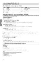
CONNECTING PERIPHERALS Description of the various peripherals Fig. 21 Key 1 2 3 4 5 6 Description Orange light Remote lighting Code keypad Keyswitch Aerial Battery Description Pedestrian door safety kit Photoelectric cells Reflex type cells Sensor bar Siren Electrical connections for the various peripherals Fig. 21 to 30 Cut the electric power supply to the motor before performing any work on peripherals. If the display remains off after working on the system, check the wiring (for possible short circuits or polarity reversals). General electrical diagram (Fig. 21) Photoelectric cells (Fig....
カタログの7ページ目を開く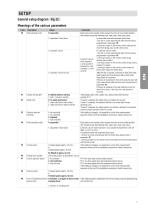
SETUP General setup diagram Fig. 31 Code P0 Description Total operating mode Values 0: sequential 1: sequential + timed close 3: automatic closure by cells Orange warning light Safety input Obstacle detection sensitivity Partial operating mode 0: without advance warning 1: with 2 s advance warning 0: no safety mechanism 1: safety mechanism with self test 2: safety mechanism without self test 0: low sensitivity 1: low sensitivity 2: standard 3: high sensitivity 0: sequential 1: sequential + timed close Closing speed Comments Each press on the remote control causes the motor to move (initial...
カタログの8ページ目を開く
Description Maintenance required indicator Detection of forced entry Safety action prior to 0: no effect opening (safety ADMAP) 1: movement rejected Safety action during closure 1: stop 2: stop + partial re-opening 3: fully reopen Obstacle detection action 2: stop + partial re-opening during closure 3: fully reopen Values 0: no indication 1: 100 cycles to 99: 9900 cycles (number of cycles = value x 100 cycles) 0: no detection of forced entry 1: obvious forced entry detected 2: less obvious forced entry detected Total operating mode automatic timed close Lighting time delay Partial operating...
カタログの9ページ目を開く
Clearing remote controls Fig. 38 Press the “PROG” button until the light blinks (7 s). This clears all of the remote controls memorised. Press the “SET” button until the light goes out (7 s). This clears all previously stored settings and returns them to their default values. Used to lock the programming settings (end limit setting, self-learning, setup). Simultaneously press the “SET”, “+” and “-” buttons: - start by pressing “SET”. - pressing “+” and “-” must take place within two seconds. To access programming mode once again, repeat the same procedure. Position the aerial and fit the...
カタログの10ページ目を開く
Error and failure codes displayed Description Safety input always active Comments Displayed when the safety input remains active for more than three minutes. Safety mechanism self test fault The safety device self test failed Other faults and failure conditions These codes correspond to various electronic circuit board failures. Detection of forced entry Detection of forced entry Displayed when an action occurs from outside the garage (read by reinjection of power) Displayed when an action occurs from outside the garage (read by optical encoder) Displayed when maintenance is required on the...
カタログの11ページ目を開くSOMFYのすべてのカタログと技術パンフレット
-
 Irismo Wirefree User Manual
116 ページ
-
 HOME ALARM PRODUCT SHEET
15 ページ
-
 GDK 700
68 ページ
-
 Situo io II
2 ページ
-
 ROLLIXO RTS
4 ページ
-
 Lighting Indoor RTS
28 ページ
-
 evohome-User-Guide
20 ページ
-
 Smart Home Brochure
12 ページ
-
 lightingoutdoor_rts
2 ページ
-
 SOMFY CATALOG
25 ページ
-
 Altus 50 RTS
2 ページ
-
 Glydea
2 ページ
-
 Irismo
2 ページ
-
 J4 1TN
2 ページ
-
 J4 2TN
2 ページ
-
 J4 HTM
2 ページ
-
 J4 RTS
2 ページ
-
 J4 WT
J4 WT2 ページ
-
 J4 io
J4 io2 ページ
-
 LS 40
LS 402 ページ
-
 LT 28
LT 282 ページ
-
 LT 50
LT 502 ページ
-
 LV25 / LW25
2 ページ
-
 Screen Job 40
2 ページ
-
 Screen Up
2 ページ
-
 Sonesse 30
2 ページ
-
 Sonesse 40 RTS
2 ページ
-
 Sonesse 50
2 ページ
-
 Sunea Screen io
2 ページ
-
 Dexxo Pro
8 ページ
-
 Sunis Flyer
2 ページ
-
 animeo IP Brochure
16 ページ
-
 ZRTSI Flyer
2 ページ
-
 TaHomA Brochure
28 ページ
-
 rts_brochure_2012
28 ページ
-
 WireFreeSolar Pack
2 ページ
-
 Awnings That Think
2 ページ


カタログアーカイブ
-
 DEXXO PRO
8 ページ