カタログの抜粋
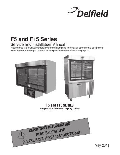
REFRIGERATED DISPLAY CASES Specifications, Installation, Operation & Maintenance Manual This manual is updated as new information and models are released. Visit our website for the latest information. Read this instruction before operating this equipment. Original Document
カタログの1ページ目を開く
Safety Notices nWarning nWarning Read this manual thoroughly before operating, installing or performing maintenance on the equipment. Failure to follow instructions in this manual can cause property damage, injury or death. DANGER Do not install or operate equipment that has been misused, abused, neglected, damaged, or altered/ modified from that of original manufactured specifications. DANGER Keep power cord AWAY from HEATED surfaces. DO NOT immerse power cord or plug in water. DO NOT let power cord hang over edge of table or counter. DANGER All utility connections and fixtures must be...
カタログの3ページ目を開く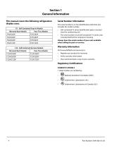
Section 1 General Information This manual covers the following refrigeration display cases. F5 - Self-Contained Drop-In Models Mirrored Back Models Pass-Thru Models F15 - Self-Contained Serview Models Mirrored Back Models Pass-Thru Models Serial Number Information The serial number is on the identification plate that also includes the model number. • Self-contained F5 series identification plate is located near the condensing unit. The serial number on all self-contained F15 series units is located behind the compressor housing. Always have the serial number of your unit available when...
カタログの4ページ目を開く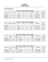
Section 2 Specifications General Specifications Mirrored F5 - Self-Contained Drop-In Models Models Shelf Area Nema Plug Ship Weight Pass Thru F5 - Self-Contained Drop-In Models Models Shelf Area Nema Plug Ship Weight Mirrored F15 - Self-Contained Serview Models Models Shelf Area Base Volume Nema Plug Ship Weight Shelf Area Base Volume Nema Plug Ship Weight Pass Thru F15 - Self-Contained Serview Models
カタログの5ページ目を開く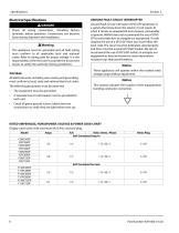
Electrical Specifications DANGER Check all wiring connections, including factory terminals, before operation. Connections can become loose during shipment and installation. nWarning This appliance must be grounded and all field wiring must conform to all applicable local and national codes. Refer to rating plate for proper voltage. It is the responsibility of the end user to provide the disconnect means to satisfy the authority having jurisdiction. VOLTAGE All electrical work, including wire routing and grounding, must conform to local, state and national electrical codes. GROUND FAULT...
カタログの6ページ目を開く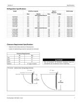
Refrigeration Specifications Model BTU/Hour Capacity Base Clearance Requirement Specifications • Keep the vents clean and clear of obstructions. Casters or optional legs must be used and not removed Clearance Requirements F5 DANGER Risk of fire/shock. All minimum clearances must be maintained. Do not obstruct vents or openings. F15 Units - Cabinet Door Swing Requirements 19" Door Front of Base Front of Top
カタログの7ページ目を開く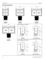
Dimension Specifications Pass Thru F5 Units - Side Profile Mirrored F5 Units - Side Profile
カタログの8ページ目を開く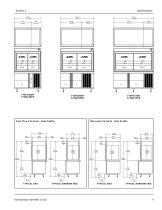
Pass Thru F15 Units - Side Profile Mirrored F15 Units - Side Profile
カタログの9ページ目を開く
Section 3 Installation DANGER Installation must comply with all applicable fire and health codes in your jurisdiction. The location selected for the equipment must meet the following criteria. If any of these criteria are not met, select another location. • Units are intended for indoor use only. The location MUST be level, stable and capable of supporting the weight of the equipment. The location MUST be free from and clear of combustible materials. Equipment MUST be level both front to back and side to side. Position the equipment so it will not tip or slide. Front casters MUST be locked...
カタログの10ページ目を開く
F15 Leg & Caster Installation DANGER Remote Option Installation F5 REMOTE MODELS Legs or casters must be installed and the legs or casters must be screwed in completely to prevent bending. When casters are installed the mass of this unit will allow it to move uncontrolled on an inclined surface. These units must be tethered/secured to comply with all applicable codes. nWarning The unit must be installed in a stable condition with the front wheels locked. Locking the front casters after installation is the owner’s and operator’s responsibility. Leveling After the cabinet has been placed in...
カタログの11ページ目を開く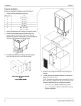
F5 Counter Installation For any non-standard installation consult the factory. 1. Cabinet interior minimum dimensions: Dimension 2. Place the condensing unit through the counter cutout. 3. Extend the telescoping duct from the front of the condensing unit to the back of the louver. This will prevent recirculation of discharge air. Export models do not have a telescoping duct, skip to step 6. 4. Put eight provided screws through the telescoping duct side walls to hold it at the desired depth. 5. Partitions must fully extend front to back and top to bottom. Use Screws to Secure Desired Depth 3...
カタログの12ページ目を開く
Section 4 Operation nWarning Do not block the supply and return air grills or the air space around the air grills. Keep plastic wrappings, paper, labels, etc. from being airborne and lodging in the grills. Failure to keep the air grills clear will result in unsatisfactory operation of the system. The on-site supervisor is responsible for ensuring that operators are made aware of the inherent dangers of operating this equipment. DANGER Do not operate any appliance with a damaged cord or plug. All repairs must be performed by a qualified service company. ,Caution Do not throw items into the...
カタログの13ページ目を開く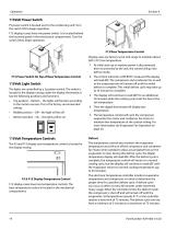
115Volt Power Switch F5 power switch is located next to the condensing unit. Turn the switch ON to begin operation. F15 displays cases have one power switch. It is located behind the louvered panel in the mechanical compartment. Turn the switch ON to begin operation. F15 Base Temperature Control Display cases are factory set at mid-range to maintain about 38ºF (3ºC) box temperature. 1. At initial start-up or anytime power is disconnected, then reconnected to the unit, the control will go into defrost mode. F15 Power Switch On Top of Base Temperature Control 115Volt Light Switch The lights...
カタログの14ページ目を開くDelfieldのすべてのカタログと技術パンフレット
-
 4400 Series
28 ページ
-
 F16DD
F16DD2 ページ
-
 Drop-Ins
8 ページ
-
 Standard Color Chart
1 ページ
-
 UTSP
UTSP2 ページ
-
 Versa Drawer
8 ページ
-
 Coolscapes
4 ページ
-
 Global Reach-Ins
4 ページ
-
 ESP
ESP2 ページ
-
 Equipement Stands
4 ページ
-
 E-Chef
2 ページ
-
 Display Case
4 ページ
-
 DFN8200ST
2 ページ
-
 DF442712M
2 ページ
-
 DB4400
4 ページ
-
 Custom Fabricantion
8 ページ
-
 Concepts
8 ページ
-
 5415 Carts and Kiosk
8 ページ
-
 TT, TT2 Shelleymatic
2 ページ
-
 FT2-SN Shelleymatic
2 ページ
-
 CT Shelleymatic
2 ページ
-
 SSHRI-G series
2 ページ
-
 Pizza Prep Tables
6 ページ
-
 Specification Line®
4 ページ
-
 Shelley
8 ページ
-
 Convochill
12 ページ
-
 4427N-12M Mega Top
2 ページ
-
 6000XL? Reach-In
6 ページ
-
 F5 and F15 Series
20 ページ
-
 LiquiTec® Cold pans
4 ページ
-
 18600PTBM
4 ページ
-
 F13 Series
12 ページ


カタログアーカイブ
-
 Drop-Ins_2012
5 ページ
-
 Drawer system
2 ページ
-
 Drop-Ins_2009
8 ページ