Swirl Diffusers
1 /17Pages

Swirl Diffusers
1 /17Pages
Catalog excerpts
2/4/EN/8 Swirl Diffusers Type RFD recommended for use in rooms with ceiling heights of approx. 2.60 . . . 4.00 m TROX GmbH Heinrich-Trox-Platz D-47504 Neukirchen-Vluyn Telephone +49 / 28 45 / 2 02-0 Telefax +49 / 28 45 / 2 02-2 65 e-mail [email protected] www.troxtechnik.com
Open the catalog to page 1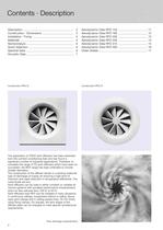
Contents • Description Construction RFD-Q The application of TROX swirl diffusers has been extended from the comfort conditioning field and has found a significant number of industrial applications. Therefore, to complete the range of FD swirl diffusers which have been so successful, the RFD range has been extended to include smaller diameters. The construction of the diffuser results in a swirling rotational type of discharge of supply air ensuring a high level of induction and rapid reduction in temperature differential. The Swirl diffusers can be used in either constant or variable air volume...
Open the catalog to page 2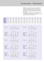
Dependant on requirements of maximum volumetric flow, noise level and installation situation, swirl diffusers are available with or without discharge nozzles. Depending on architectural demands the face can be circular or square. Duct connection details for the type RFD swirl diffuser are shown below. For types RFD-...-UO or RFD-...-UD, the top entry plenum box supplied includes the internal subframe. In this configuration the diffuser face is held in position by a central fixing bolt which has a decorative cap. perforated plate perforated plate perforated plate perforated plate perforated plate...
Open the catalog to page 3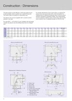
Construction • Dimensions The face section of the diffuser or side entry plenum box is demountable, held in position by a central fixing bolt. The screw head is covered by a decorative cap. The plenum box can be supplied with a volume control For type RFD-...-D-N (which is only available with discharge nozzle), the plenum box and diffuser face form an integral For simple adjustment of the volume flow, on request the plenum box can be provided with a test connection for measurement of reference pressures and a volume control damper, operated by sheathed cables. The characteristic curve of pressure...
Open the catalog to page 4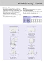
Installation • Fixing Because of their excellent performance, type RFD swirl diffusers can be installed flush with a continuous ceiling or freely suspended (with discharge nozzle). Installation is also possible on stub ducts or suspended above a grid ceiling. For the suspended versions of the top or side entry plenums neck, transition piece and plenum box are fitted with suspension holes resp. suspension lugs. For ceiling panels up to 20 mm thickness, clamp fixing is possible without additional support from the slab ceiling Ensure that the ceiling panels are stable. The diffuser face and side...
Open the catalog to page 5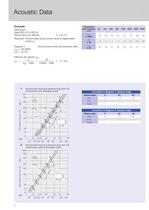
Data given: Volume flow per diffuser V = 24 l/s Required: Octave band sound power level of regenerated Diagram 1: Sound power level and pressure drop Effective jet velocity veff: Correction to Diagram 1: Damper angle 1 Sound power level and pressure drop Size 125 Construction with discharge nozzle 2 Sound power level and pressure drop Size 125 Construction without discharge nozzle
Open the catalog to page 7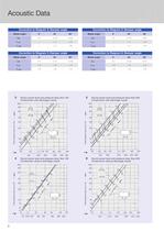
Acoustic Data 3 Sound power level and pressure drop Size 160 Construction with discharge nozzle 5 Sound power level and pressure drop Size 200 Construction with discharge nozzle 6 Sound power level and pressure drop Size 200 Construction without discharge nozzle
Open the catalog to page 8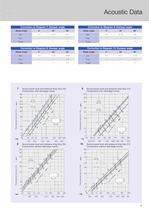
Acoustic Data Correction to Diagram 7: Damper angle Correction to Diagram 9: Damper angle Correction to Diagram 8: Damper angle H Correction to Diagram 10: Damper angle 7 Sound power level and pressure drop Size 250 Construction with discharge nozzle 8 Sound power level and pressure drop Size 250 Construction without discharge nozzle 9 Sound power level and pressure drop Size 315 Construction with discharge nozzle 10 Sound power level and pressure drop Size 315 Construction without discharge nozzle
Open the catalog to page 9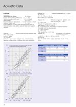
Acoustic Data Example Data given: · Volume flow per diffuser V = 30 l/s Supply air temperature differential ͬ t Z = – 8 K Sound pressure level in room L A = 40 dB(A) Room height H = 3.0 m Required: spacing dimensions A x B = 3.20 m x 3.20 m Distance to side wall X = 1.60 Flush installation in ceiling with discharge nozzle. Due to restricted ceiling void, plenum box with side entry spigot is required. Diagram 1: Sound power level and pressure drop RFD-R-D-A /125 L WA = 37 dB(A) ͬ p t = 40 Pa To arrive at room sound pressure level, corrections are required for the number of diffusers and room absorption....
Open the catalog to page 10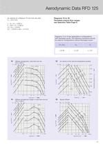
Air velocity at a distance 75 mm from the wall Permitted volume flow ranges see Selection Table Page 6. Diagrams 13 to 16 are applicable to configurations with discharge nozzle. The following corrections should be used for configurations without discharge nozzle: 13 Diffuser arrangement: more than one row 14 Diffuser arrangement: single or more than one row 15 Air velocity at the wall and temperature quotient
Open the catalog to page 11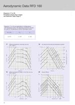
Permitted volume flow ranges see Selection Table Page 6. Diagrams 17 to 20 are applicable to configurations with discharge nozzle. The following corrections should be used for configurations without discharge nozzle: 17 Diffuser arrangement: more than one row 18 Diffuser arrangement single or more than one row 19 Air velocity at the wall and temperature quotient
Open the catalog to page 12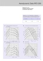
Permitted volume flow ranges see Selection Table Page 6. Diagrams 21 to 24 are applicable to configurations with discharge nozzle. The following corrections should be used for configurations without discharge nozzle: 21 Diffuser arrangement: more than one row 22 Diffuser arrangement: single or more than one row 23 Air velocity at the wall and temperature quotient
Open the catalog to page 13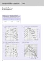
Permitted volume flow ranges see Selection Table Page 6. Diagrams 25 to 28 are applicable to configurations with discharge nozzle. The following corrections should be used for configurations without discharge nozzle: 25 Diffuser arrangement: more than one row 26 Diffuser arrangement: single or more than one row 27 Air velocity at the wall and temperature quotient
Open the catalog to page 14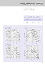
Permitted volume flow ranges see Selection Table Page 6. Diagrams 29 to 32 are applicable to configurations with discharge nozzle. The following corrections should be used for configurations without discharge nozzle: 29 Diffuser arrangement: more than one row 30 Diffuser arrangement: single or more than one row 31 Air velocity at the wall and temperature quotient
Open the catalog to page 15All TROX catalogs and technical brochures
 Retrofit kits
6 Pages
 X-GRILLE Cover
18 Pages
 QUICK SELECTION GUIDE 2019 - 2
804 Pages
 QUICK SELECTION GUIDE 2019 - 1
530 Pages
 ATVC-100
8 Pages
 X-CUBE Compact
12 Pages
 X-CUBE RUN AROUND COIL SYSTEM
10 Pages
 Air-water systems
307 Pages
 ARR
ARR2 Pages
 WT · WL · EL
8 Pages
 VMRK
VMRK4 Pages
 VFR
VFR8 Pages
 Tunnel dampers
20 Pages
 FKS-EU
20 Pages
 CAK
CAK6 Pages
 Type ST · XT
8 Pages
 Type ARK · ARK1
8 Pages
 Type NL
8 Pages
 Type JZ · JNE · JZ-L · JZD-G
20 Pages
 Type FSL-B-ZAB
4 Pages
 Type PKV
7 Pages
 Type BID
8 Pages
 Type QLI
8 Pages
 TVJ-Easy/TVT-Easy
12 Pages
 LVC
LVC9 Pages
 RM-O-3-D
7 Pages
 RM-O-VS-D
7 Pages
 FK-EU
FK-EU56 Pages
 EK-01
EK-0114 Pages
 XSA
XSA12 Pages
 MSA
MSA12 Pages
 SCHOOLAIR-V
12 Pages
 SCHOOLAIR-B
12 Pages
 FSL-B-SEK
4 Pages
 DID632
20 Pages
 DID300B
12 Pages
 DID312
16 Pages
 AGW
AGW24 Pages
 AGS
AGS24 Pages
 DLQ-1...4-AK
13 Pages
 DQ/ADQ
9 Pages
 DLQ/ADLQ
10 Pages
 DLK-Fb
4 Pages
 VD
VD10 Pages
 QSH · ISH
8 Pages
 DLQL
DLQL12 Pages
 X-CUBE
16 Pages
 FV-K90
12 Pages
 TVR-Ex _ TES/TEF
7 Pages
 AK-Ex
AK-Ex5 Pages
 JZ-RS
JZ-RS5 Pages
 FKRS-EU
28 Pages
 Multileaf Dampers
8 Pages
 Star Climate
16 Pages
 X-GRILLE-Basic
4 Pages
 X-GRILLE-Basic
3 Pages
 Jet nozzles TJN
3 Pages
 ARCHITECTURE NEEDS TO BREATHE
16 Pages
 SD
SD10 Pages
 AIRNAMIC
12 Pages
 XARTO
XARTO12 Pages
 X-CUBE COMPACT
10 Pages


Archived catalogs
 Product Summary
7 Pages
 Displacement Flow Diffusers
32 Pages
 Quick selection guide
48 Pages
 The art of handling air
80 Pages
 Air-water systems Design manual
60 Pages
 Slot Diffuser
11 Pages
 Grilles/Linear Grilles
24 Pages
 Passive Chilled Beams
7 Pages
 Swirl Diffusers Type FDE
6 Pages
 Swirl Diffuser Type VDW
20 Pages


- Ventilation grill
- Metal ventilation grill
- Rectangular ventilation grill
- Industrial air diffuser
- Aluminum ventilation grill
- Square ventilation grill
- Ceiling-mounted air diffuser
- Air handling unit
- Circular displacement air diffuser
- Square air diffuser
- Air filter
- Ventilation damper
- Commercial air handling unit
- Adjustable ventilation grill
- Linear air diffuser
- Metal ventilation damper
- Slot air diffuser
- Industrial air handling unit
- Linear ventilation grill
- Steel ventilation grill